SKM500GA174D –ü—Ä–æ—Å–º–æ—Ç—Ä —Ç–µ—Ö–Ω–∏—á–µ—Å–∫–æ–≥–æ –æ–ø–∏—Å–∞–Ω–∏—è (PDF) - Semikron
–ù–æ–º–µ—Ä –≤ –∫–∞—Ç–∞–ª–æ–≥–µ
–ö–æ–º–ø–æ–Ω–µ–Ω—Ç—ã –û–ø–∏—Å–∞–Ω–∏–µ
–ø—Ä–æ–∏–∑–≤–æ–¥–∏—Ç–µ–ª—å
SKM500GA174D Datasheet PDF : 6 Pages
| |||
SKM 500 GA 174 D
Absolute Maximum Ratings
Symbol Conditions 1)
VCES
VCGR
IC; ICN
ICM
VGES
Ptot
Tj, (Tstg)
Visol
humidity
climate
RGE = 20 kΩ
Tcase = 25/80 °C
Tcase = 25/80 °C; tp = 1 ms
per IGBT, Tcase = 25 °C
AC, 1 min. 4)
IEC 60721-3-3
IEC 68 T.1
Inverse Diode 8)
IF = –IC Tcase = 25/80 °C
IFM = –ICM Tcase = 25/80 °C; tp = 1 ms
IFSM
tp = 10 ms; sin.; Tj = 150 °C
I2t
tp = 10 ms; Tj = 150 °C
Values
1700
1700
600 / 440 5)
1200 / 880
± 20
3100
–40 ... +150 (125)
3400
class 3K7/IE32
40/125/56
600 / 440
1200 / 880
4400
96800
Units
V
V
A
A
V
W
°C
V
A
A
A
A2s
Characteristics
Symbol Conditions 1)
V(BR)CES
VGE(th)
ICES
IGES
VCEsat
gfs
VGE = 0, IC = 8 mA
VGE = VCE, IC = 18 mA
VGE = 0
Tj = 25 °C
VCE = VCES Tj = 125 °C
VGE = 20 V, VCE = 0
IC = 400 A VGE = 15 V;
IC = 500 A Tj = 25 (125) °C
VCE = 20 V, IC = 400 A
CCHC
Cies
Coes
Cres
LCE
per IGBT
VGE = 0
VCE = 25 V
f = 1 MHz
td(on)
tr
td(off)
tf
Eon
Eoff
VCC = 1200 V
VGE = –15 V / +15 V 3)
IC = 400 A, ind. load
RGon = RGoff = 3 Ω
Tj = 125 °C (VCC = 900 V/1200 V)
LS = 60 nH (VCC = 900 V/1200 V)
Inverse Diode 8)
min.
‚â• VCES
4,5
–
–
–
–
–
–
–
–
–
–
–
–
–
–
–
–
–
VF = VEC IF = 400 A VGE = 0 V;
–
VF = VEC IF = 500 A Tj = 25 (125) °C
–
VTO
Tj = 125 °C
–
rt
Tj = 125 °C
–
IRRM
IF = 400 A; Tj = 25 (125) °C2)
–
Qrr
IF = 400 A; Tj = 25 (125) °C2)
–
Thermal characteristics
Rthjc
per IGBT
–
Rthjc
per diode D
–
Rthch
per module
–
typ.
–
5,5
0,1
16
–
2,8(3,2)
3,1(3,7)
220
–
27
3,8
1,3
–
350
100
1100
100
170/300
135/210
2,15(1,8)
2,3(2,0)
1,3
1,6
270(550)
70(117)
–
–
–
max.
–
6,5
1
–
0,3
3,3(3,6)
–
–
1,4
–
–
–
20
–
–
–
–
–
–
2,4(2,2)
–
1,5
2,1
–
–
0,040
0,070
0,038
Units
V
V
mA
mA
µA
V
V
S
nF
nF
nF
nF
nH
ns
ns
ns
ns
mWs
mWs
V
V
V
mΩ
A
µC
°C/W
°C/W
°C/W
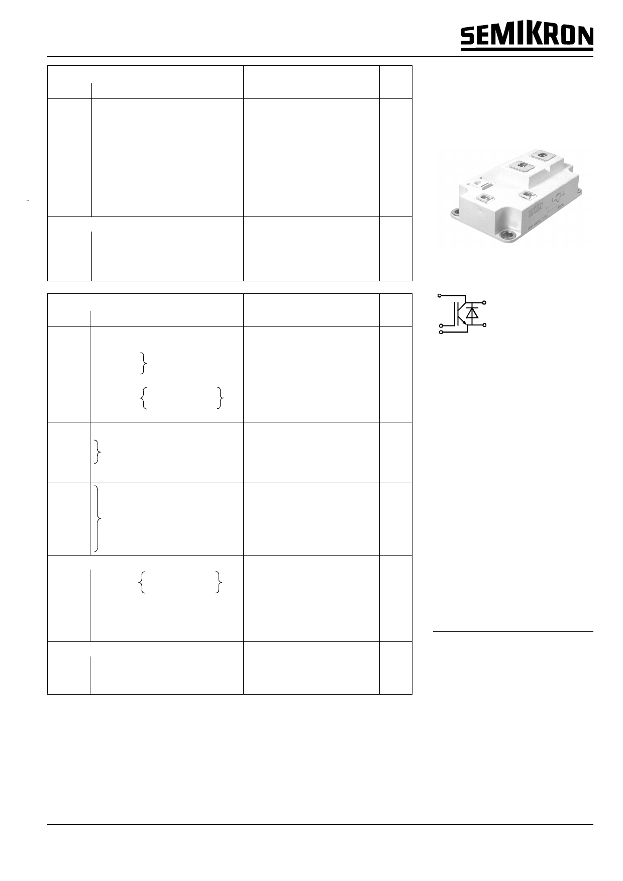
SEMITRANS® M
Low Loss IGBT Modules
SKM 500 GA 174 D
SEMITRANS 4
GA
Features
• N channel, homogeneous Silicon
structure (NPT- Non punch-
through IGBT)
• Low inductance case
• High short circuit capability,
self limiting
• Fast & soft inverse CAL diodes 8)
• Without hard mould
• Large clearance (13 mm) and
creepage distances (20 mm)
Typical Applications
• AC inverter drives on mains
575 - 750 VAC
• DC bus voltage 750 - 1200 VDC
• Public transport (auxiliary syst.)
• Switching (not for linear use)
1) Tcase = 25 °C, unless otherwise
specified
2) IF = – IC, VR = 1200 V,
–diF/dt = 5000 A/µs, VGE = 0 V
3) Use VGEoff = – 5 ... – 15 V
4) Option Visol = 4000V/1 min add suffix
„H4“ - on request
5) Limited by terminals to IC(DC) = 500 A
at Tc = Tterminal ≤ 100 °C
8) CAL = Controlled Axial Lifetime
Technology
© by SEMIKRON
000828
B 6 – 73
Share Link: 