SGM9111ZS Просмотр технического описания (PDF) - Shengbang Microelectronics Co, Ltd
Номер в каталоге
Компоненты Описание
производитель
SGM9111ZS Datasheet PDF : 9 Pages
| |||
Application Information
The SGM9111 low cost, integrated, 3-pole, video filter is
intended to replace passive LC filters and drivers in low voltage
portable video applications. The 3-pole filter provides better
image quality compared to typical 2-pole solutions.
The SGM9111 input must be AC-coupled because the input
capacitor stores the clamp voltage. It needs a typical value of
0.1µF for the input clamp to meet the Line Droop specification.
The SGM9111 output can drive an AC or DC-coupled doubly
terminated coax (150Ω) load(see Figure 1). DC-coupling the
output removes the need for an expensive and large output
coupling capacitor(see Figure 2).
Internal Sync Clamp
The typical embedded video DAC operates from a ground
referenced single supply. This becomes an issue because the
lower level of the sync pulse output may be at a 0V reference
level to some positive level. The problem is presenting a 0V
input to most single supply driven amplifiers will saturate the
output stage of the amplifier resulting in a clipped sync tip and
degrading the video image. A larger positive reference may
offset the input above its positive range.
The SGM9111 features an internal sync clamp and offset
function to level shift the entire video signal to the best level
before it reaches the input of the amplifier stage. These
features are also helpful to avoid saturation of the output stage
of the amplifier by setting the signal closer to the best voltage
range.
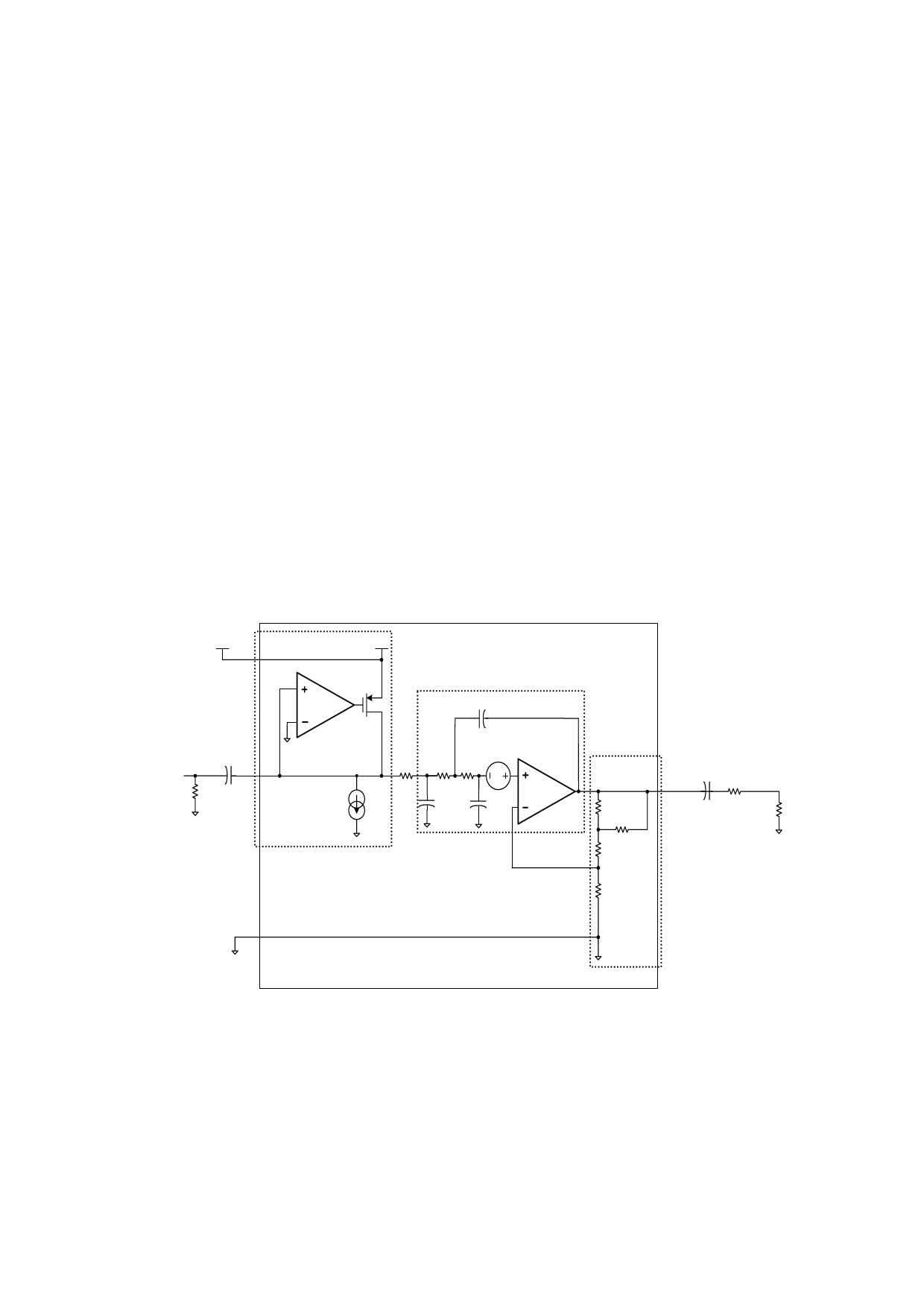
The typical Application diagram of the SGM9111 in Figure 1 is
divided into four sections. The first, Section A is the Sync
Clamp. The AC coupled video sync signal is pulled negative by
a current source at the input of the comparator amplifier. When
the sync tip goes below the comparator threshold the output
comparator is driven negative, The PMOS device turns on
clamping sync tip to near ground level. The network triggers on
the sync tip of video signal.
+VS
+VS
+VS
0.1µF
IN
IN
RIN CIN
SYNC CLAMP
C3
VDC
R1
R2 R3
C1
C2
SALLEN KEY LOW
PASS FILTER
R4
R5
R6
R7
COUT = 220µF
OUT
ROUT = 75Ω
RL = 75Ω
GND
SAG NETWORK
Figure 1. Typical Application Diagram
6
SGM9111
Share Link: 