SG2548J(2005) Просмотр технического описания (PDF) - Microsemi Corporation
Номер в каталоге
Компоненты Описание
производитель
SG2548J Datasheet PDF : 4 Pages
| |||
SG1548/SG2548/SG3548
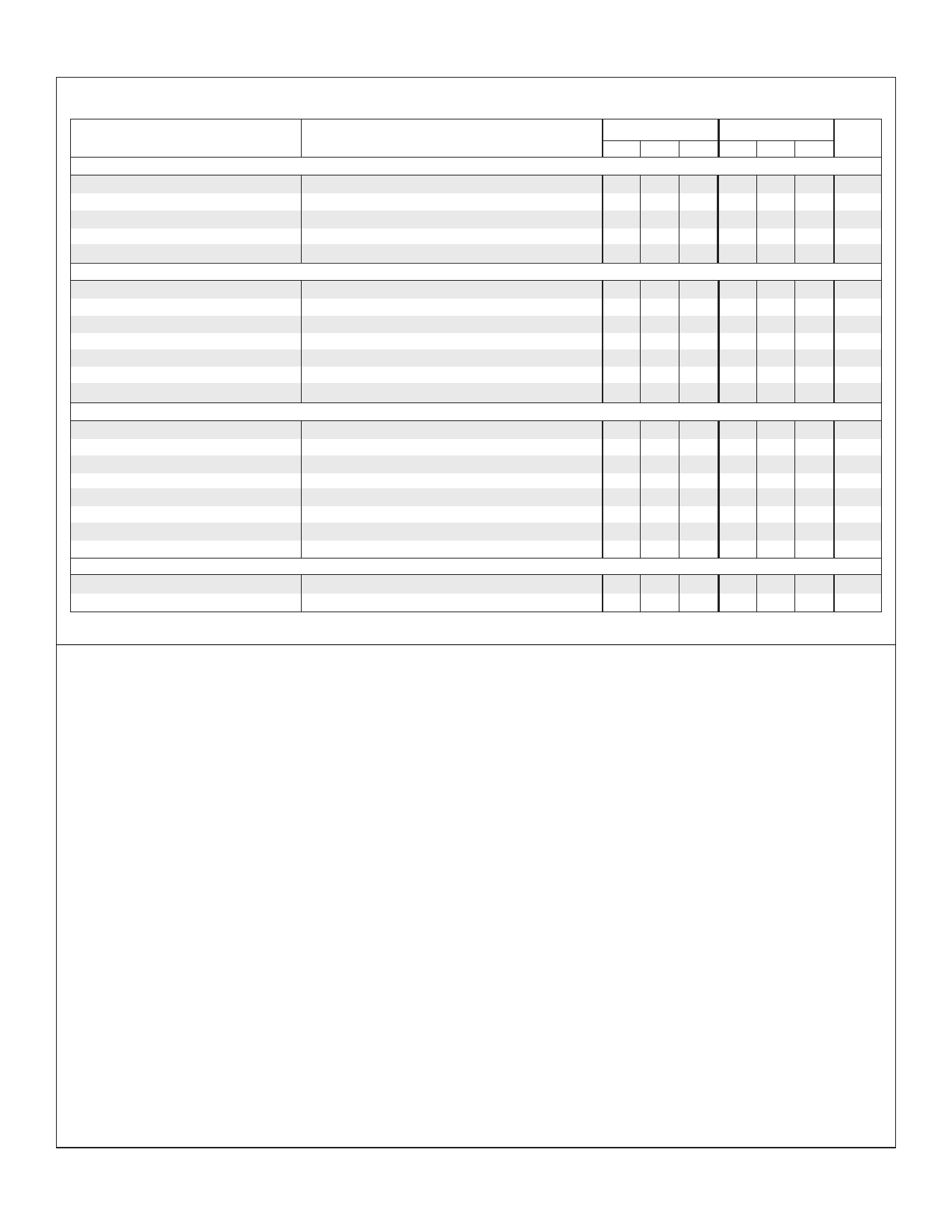
ELECTRICAL CHARACTERISTICS (continued)
Parameter
Test Conditions
Fault Delay Section
Comparator Threshold
Comparator Hysteresis
Delay Charging Current
On Saturation Voltage
OFF Clamp Voltage
V = 0V
PIN 8
IPIN 8 = 0mA
IPIN 8 = 0mA
Inverting Op Amp Section (Note 5)
Input Offset Voltage
Input Bias Current
Output High Voltage
Output Low Voltage
Large Signal Voltage Gain
Output Source Current
Power Supply Rejection Ratio
AC Line Sense Section
ISOURCE = 5mA
I = 5mA
SINK
RL = 10K
+V = 4.5V to 35V
IN
Comparator Threshold
Comparator Hysteresis
V = Low to High
PIN 5
Input Bias Current
VPIN 5 = 2.5V
Collector Leakage Current
VCE = 40V
Collector Saturation Voltage
IC = 10mA
Emitter Output Voltage
IE = 10mA
Diode Clamp Voltage
IPIN 5 = 1mA
IPIN 5 = -1mA
Fault Logic Outputs (Each output)
Collector Leakage Current
Collector Saturation Voltage
VC = 40V
IC = 10mA
Note 5. +V = 4.5V.
IN
SG1548/2548
SG3548
Min. Typ. Max. Min. Typ. Max. Units
1.200 1.250 1.300 1.200 1.250 1.300 V
25
25
mV
32.5 50 67.5 32.5 50 67.5 µA
0.1 0.2
0.1 0.2 V
+3.2 +3.6
+3.2 +3.6 V
2 15
2 15 mV
-0.3 -1.0
-0.3 -1.0 µA
3.2 3.5
3.2 3.5
V
1.0 1.9
1.0 1.9 V
72 100
72 100
dB
5 15 25 5 15 25 mA
72 100
72 100
dB
2.440 2.500 2.560 2.440 2.500 2.560 V
25
25
mV
12
1 2 µA
1 10
1 10 µA
0.2 0.5
0.2 0.5 V
12 13
12 13
V
6.0
7.5 6.0
7.5 V
-0.3
-1.0 -0.3
-1.0 V
1 10
0.2 0.5
1 10 µA
0.2 0.5 V
APPLICATION INFORMATION
SETTING THE FAULT TOLERANCE WINDOW
MONITORING A NEGATIVE VOLTAGE
The fault tolerance window is set by applying a voltage less than
the +2.50Vreference to the Lower Threshold input (Pin 1). The
voltage is obtained by a resistor divider from the reference (Pin 3)
to ground. If ±5% tolerance is desired, then 95% of the reference
(+2.375V) is applied to Pin 1. If ±40% is wanted, then 60% of the
reference (+1.50V) is applied. In the example on the back page,
the tolerance is ±5%. The nominal overvoltage and undervoltage
thresholds are centered about the reference at +2.625V and
+2.375V (+2.500V ±0.125V).
SCALING THE MONITORED SUPPLY VOLTAGES
A negative voltage can be converted to a positive one and
simultaneously scaled to +2.50V by using the internal operational
amplifier as an inverter. Only an input resistor and feedback
resistor are required.
SETTING THE FAULT DELAY
A single capacitor at the Delay pin sets the time an out-of-
tolerance fault must persist before a fault is actually declared.
This feature allows switching noise on the supplies to be rejected.
The delay time is given by: Delay = 25ms/µF .
Each positive voltage to be monitored is divided down to +2.50V
with a resistor network and connected to one of the Sense inputs.
Unused Sense inputs should be connected to the reference. This
will not increase the bias current. A variation of the monitored
voltages out of the programmed tolerance range will cause the
appropriate overvoltage or undervoltage fault output to switch
LOW. The effective tolerance on any input may be broadened
with an additional resistor to the voltage reference. The example
on the back page shows a ±10% tolerance on the +5Vsupply
although the SG1548 is programmed for a ±5% tolerance. The
procedure for calculating the resistor value is found in the
SG1548 Application Note.
AC LINE MONITORING
The AC line voltage can be monitored for single-cycle dropouts
with the few components shown in the example. A half-wave
rectifier charges the capacitor on positive line cycles. After the
positive peak and during the negative line cycle the capacitor
discharges from a fixed voltage controlled by the internal Zener
diode. If a positive cycle is missing, the capacitor discharges to
below the +2.5V trip point of the comparator, causing the output
transistor to turn on.
Rev 1.2a
Copyright © 1997
11861 Western Avenue ∞ Garden Grove, CA 92841
3
(714) 898-8121 ∞ FAX: (714) 893-2570
Share Link: 