ATSAM4S16BA-AU Просмотр технического описания (PDF) - Atmel Corporation
Номер в каталоге
Компоненты Описание
производитель
ATSAM4S16BA-AU Datasheet PDF : 67 Pages
| |||
SAM4S Series [Preliminary]
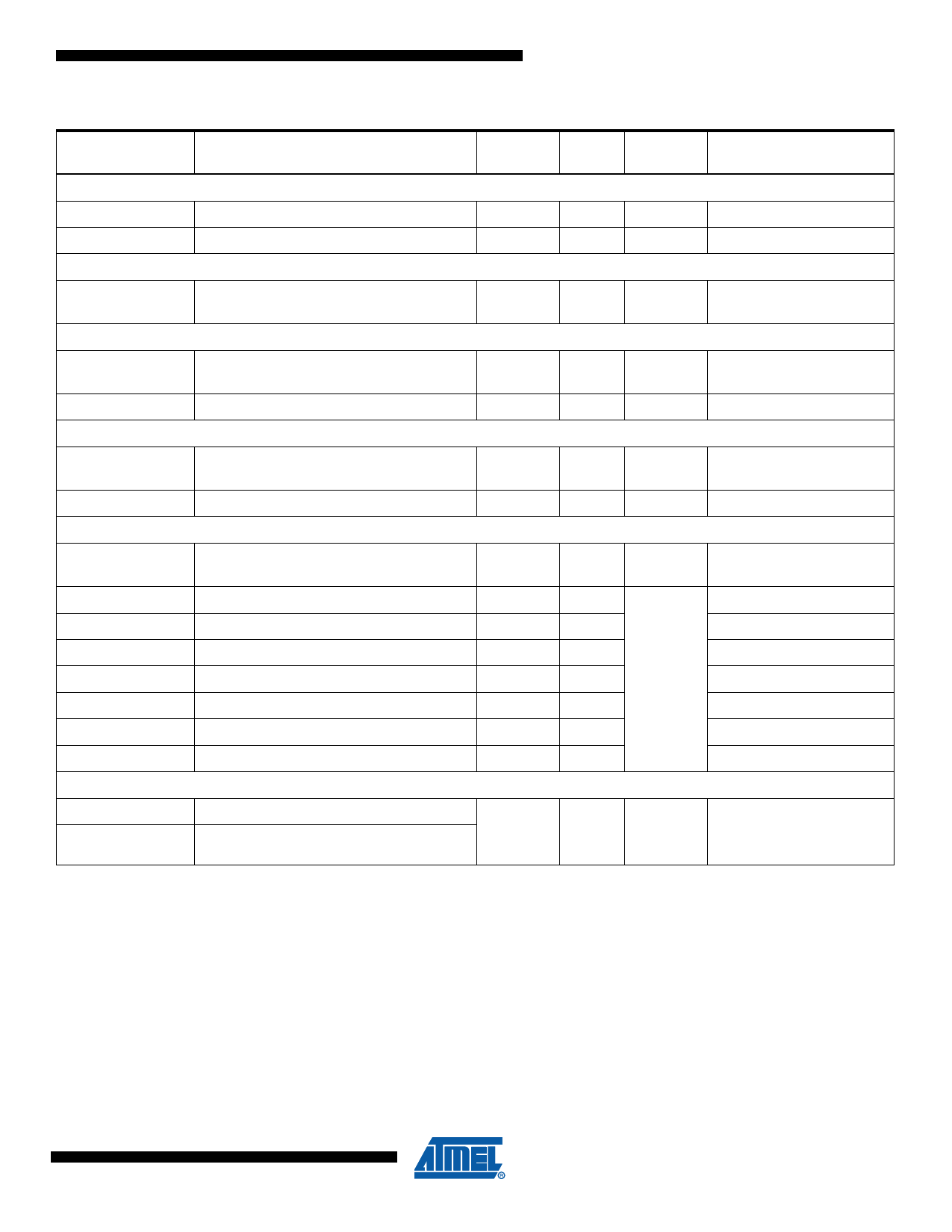
Table 3-1. Signal Description List (Continued)
Signal Name
Function
Type
Active
Level
Two-Wire Interface- TWI
TWDx
TWIx Two-wire Serial Data
I/O
TWCKx
TWIx Two-wire Serial Clock
I/O
Analog
ADVREF
ADC, DAC and Analog Comparator
Reference
Analog
12-bit Analog-to-Digital Converter - ADC
AD0-AD14
Analog Inputs
Analog,
Digital
ADTRG
ADC Trigger
Input
12-bit Digital-to-Analog Converter - DAC
DAC0 - DAC1
Analog output
Analog,
Digital
DACTRG
DAC Trigger
Input
Fast Flash Programming Interface - FFPI
PGMEN0-
PGMEN2
Programming Enabling
Input
PGMM0-PGMM3 Programming Mode
Input
PGMD0-PGMD15 Programming Data
I/O
PGMRDY
Programming Ready
Output
High
PGMNVALID
Data Direction
Output
Low
PGMNOE
Programming Read
Input
Low
PGMCK
Programming Clock
Input
PGMNCMD
Programming Command
Input
Low
USB Full Speed Device
DDM
DDP
USB Full Speed Data -
USB Full Speed Data +
Analog,
Digital
Voltage
reference
VDDIO
VDDIO
VDDIO
VDDIO
VDDIO
Comments
Reset State:
- USB Mode
- Internal Pull-down(3)
Note:
1. Schmitt Triggers can be disabled through PIO registers.
2. Some PIO lines are shared with System I/Os.
3. Refer to USB Section of the product Electrical Characteristics for information on Pull-down value in USB Mode.
4. See “Typical Powering Schematics” Section for restrictions on voltage range of Analog Cells.
5. TDO pin is set in input mode when the Cortex-M4 Core is not in debug mode. Thus the internal pull-up corresponding to this
PIO line must be enabled to avoid current consumption due to floating input.
11
11100BS–ATARM–31-Jul-12
Share Link: 