SAA7392 Просмотр технического описания (PDF) - Philips Electronics
Номер в каталоге
Компоненты Описание
производитель
SAA7392 Datasheet PDF : 76 Pages
| |||

Philips Semiconductors
Channel encoder/decoder CDR60
Preliminary specification
SAA7392
7.4 HF analog front-end
The HF ADC in the SAA7392 encodes the EFM high
frequency signal from the disc light pen assembly. These
signals are pre-processed, externally to the SAA7392, by
either AEGER-2 or a DALAS equivalent. The dynamic
range of the ADC is optimized by the inclusion of an
AC coupled AGC function under digital control.
In order to make use of the whole digital front-end
resolution, the output of the gain control amplifier should
constantly deliver 1.4 V(p-p) output signal. The gain range
of the ADC is approximately 14 dB, with 32 steps. The gain
control for the variable gain amplifier is controlled by an
on-chip digital gain control block (AGC). This block allows
for both automatic and microprocessor gain control. The
gain control block will detect ADC extreme conditions
(00H or FFH outputs); on these values the gain control
block will decrement the gain. If no extreme codes occur
the gain is incremented.
7.4.1 FIXED GAIN
Control of the gain is as follows:
1. Writing XX1X XXXX to the Anaset1 register
(address 15H) increases the AGC gain by 1.1 dB
2. Writing XX0X XXXX to the AnaSet1 register
(address 15H) decreases the AGC gain by 1.1 dB
3. Instructions to increment/decrement gain are ignored
when the AGC gain limits of −4/+12 dB are reached.
7.4.2 AUTOMATIC GAIN CONTROL (AGC)
The gain of the AGC cell is adjusted until the analog signal
at the ADC input extends over the complete range of
the ADC. Detection of this condition is in the digital domain
where the maximum and minimum ADC codes are
measured. The dynamics of the AGC system are as
follows.
1. If the ADC output codes are not full scale (i.e.
000 0000 and 111 11111) the AGC gain is
incremented in 1.1 dB steps with a time constant of
1000/n µs, where n is the over-speed factor i.e. n = 1
for basic audio CD.
2. When full scale is detected at the output of the ADC
the AGC gain is fixed provided that full scale is
maintained and clipping does not occur for greater
than 20% of the time.
3. If clipping occurs for more than 20% of the time, then
the AGC gain is reduced in 1.1 dB steps with a time
constant of 60/n µs.
The ADC and AGC electrical characteristics are specified
in Chapter 9.
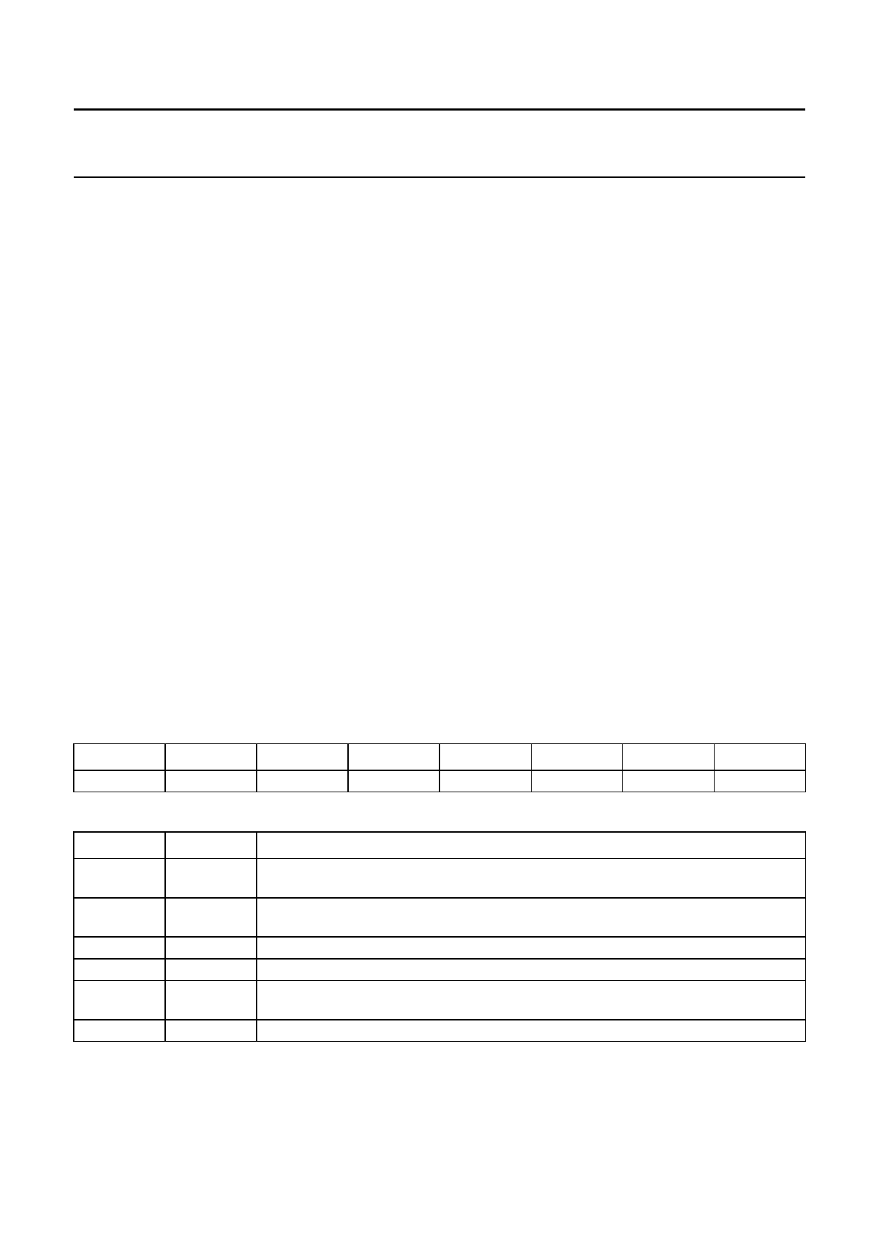
7.4.3 ANALOG SETTINGS REGISTER 1 (ANASET1)
Table 21 Analog Settings Register 1 (address 15H) - WRITE
7
6
5
4
3
2
1
0
GainControl MaxGain
StepUp
StepDown PowerDown
−
−
−
Table 22 Description of AnaSet1 bits
BIT
7
6
5
4
3
2 to 0
SYMBOL
DESCRIPTION
GainControl If GainControl = 0, then gain control is in Hold mode. If GainControl = 1, then automatic
gain control is on.
MaxGain If MaxGain = 0, then there is no gain limit. If MaxGain = 1, then the maximum gain is
7.66 dB.
StepUp If StepUp = 1, then step up gain by one LSB.
StepDown If StepDown = 1, then step down gain by one LSB.
PowerDown If PowerDown = 0, then analog blocks are powered up. If PowerDown = 1, then analog
blocks are powered down.
−
These 3 bits are reserved and must be set to a logic 0s.
2000 Mar 21
18