S553-6500-F4 Просмотр технического описания (PDF) - Bel Fuse Inc.
Номер в каталоге
Компоненты Описание
производитель
S553-6500-F4 Datasheet PDF : 4 Pages
| |||
HIGH FREQUENCY MAGNETICS
T1/E1 Dual Hybrid Transformer Module
TM01125
APPLICATION NOTES
The S553-6500-F4 hybrid transformer module contains two identical balanced hybrid transformers. Each balanced
hybrid is arranged in a symmetrical 4-port configuration, which provides low loss for preferred paths and high loss in
non-preferred (transhybrid) paths:
Bi-directional
Preferred Paths
Bi-directional
Non-preferred Paths
Port A to Port B
Port A to Port C
Port A to Port D
Port B to Port C
Port D to Port B
Port D to Port C
Normally, each hybrid is used as a 3-port device and the fourth port is terminated in a resistor whose value is equal
to the line impedance (100 Ω for T1, 75 Ω or 120 Ω for E1). While each hybrid is designed to handle balanced lines,
it will also handle a 75 Ω unbalanced line as well. In this case, R1 should be set to 75 Ω and should be left floating
as it is for the balanced lines also.
In operation, a signal at Port A is divided equally at Ports B and C with half of its original power appearing at Port B
and half at Port C. Signal isolation between splitting Ports B and C is very high at the fundamental T1 and E1 pulse
repetition frequencies. In fact, the signal isolation is typically greater than 55 dB from 500 kHz to 5 MHz. This allows
equipment connected at one of the splitting ports to be shorted or opened with virtually no effect on the signal at
the other port. In the preferred paths, the insertion loss is very low – typically less than 0.2 dB. This value is added
to the theoretical half-power or 3 dB value that results from the equal signal split to obtain a total insertion loss of
3.2 dB from input to either output.
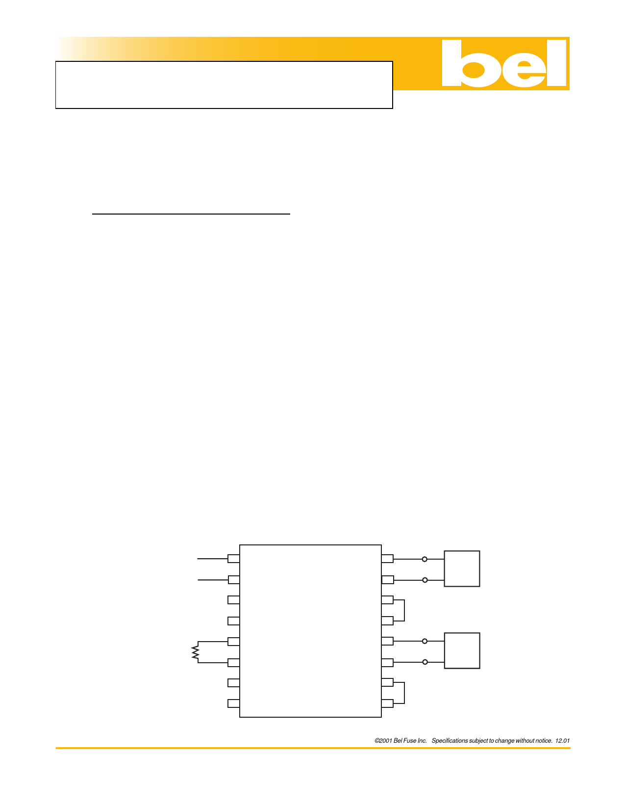
A typical signal-splitting application is shown below. A single input signal is applied at the ASIG inputs of Port A and
is split equally at the BSIG and CSIG outputs of Ports B and C.
TYPICAL APPLICATION
Half of S553-6500-F4
100 Ω
Line Port A
Input
R1 Port D
100 Ω
1 ASIG+
2 ASIG-
3
4
5 DSIG+
6 DSIG-
7
8
BSIG+ 32
BSIG- 31
COM 1 30
COM 2 29
CSIG+ 28
CSIG- 27
COM 3 26
COM 4 25
Port B
Port C
LIU 1
LIU 2
©2001 Bel Fuse Inc. Specifications subject to change without notice. 12.01
Bel Fuse Inc. 206 Van Vorst Street, Jersey City, NJ 07302 • Tel 201-432-0463 • Fax 201-432-9542 • www.belfuse.com
page 3
Share Link: 