RTC-58323 Просмотр технического описания (PDF) - Seiko Epson Corp
Номер в каталоге
Компоненты Описание
производитель
RTC-58323 Datasheet PDF : 12 Pages
| |||
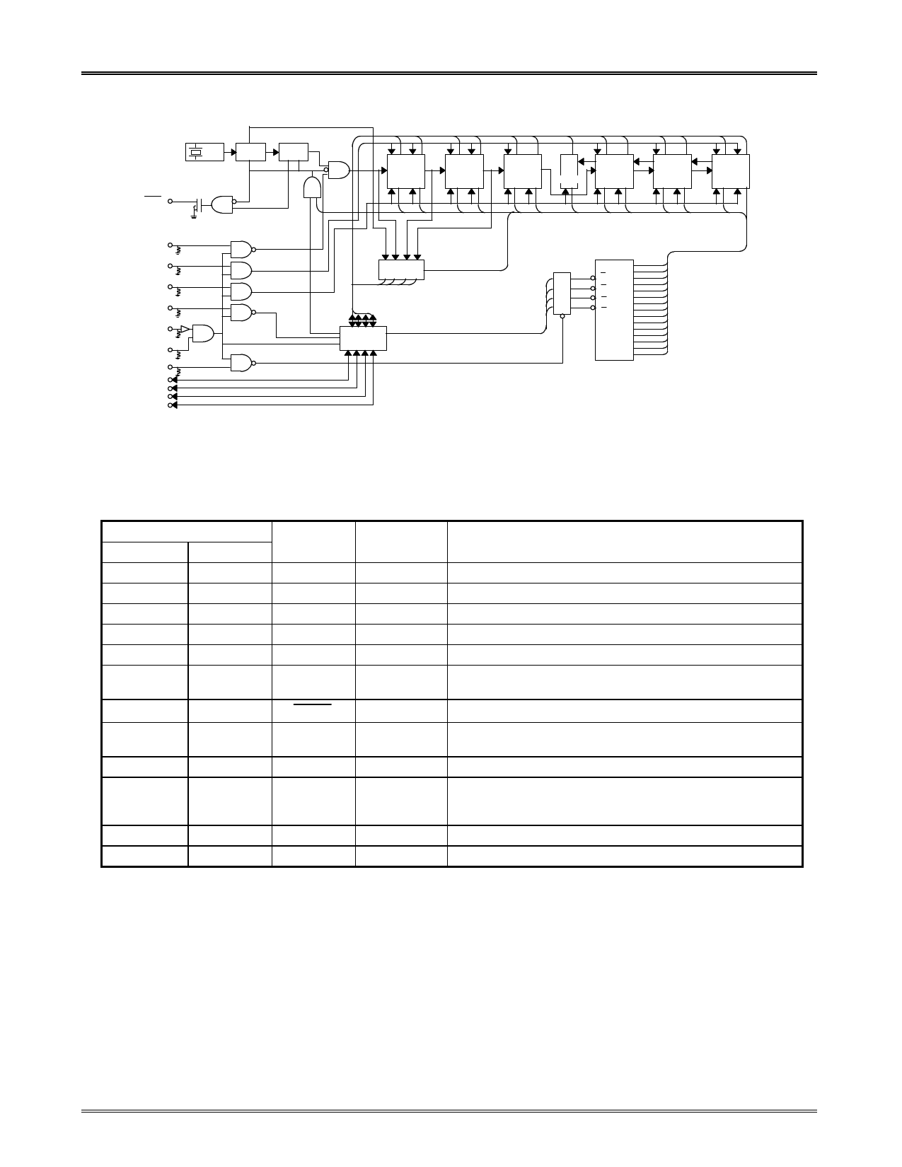
RTC-58321/58323
n Block diagram
32.768 kHz
quarts oscillator
OSC
1/215
R
BUSY
N
STOP
TEST
WRITE
READ
CS1
CS2
ADDRESS
WRITE
D0
D1
D2
D3
R1’
R1’
R1’
R1’
R1’
R1’
R1’
1024Hz
BUSY
R
D
TEST
DATA BUS
1Hz
1/10|1/6
Seconds
1/10|1/6
Minutes
or
1/12|1/24
Hours
1/7
Day-of week
S10
S1
M11 M110
H1 H10
W
1Hz 1/60Hz
1/3600Hz
1024H
z
1/10|1/3
Day
D1 D10
1/12
Month
1/10|1/10
Year
MO1 MO10
Y1 Y10
SWITCH
E, F
TRI-STATE
CONTROL
ADDRESS
LATCH
D10’
D11’
D12’
D13’
0
1
A1' 2
3
A1 4
5
A2 6
A3 7
8
9
A
B
C
D
E-F
S1
S10
M11
M110
H1
H10
W
D1
D10
M01
M010
Y1
Y10
D
E-F
u Rp = 200KΩ TYP
n Pin functions
Pin numbers
RTC-58321 RTC-58323
1
5
2
6
3
7
4 to 7
8 to 11
8
12
9
13
10
14
11
15
12
16
13
17
*
14 to 16
1 to 4
18 to 24
Pin symbol Input/output
Function
CS2
WRITE
Input
Input
Chip select. When high, device can be accessed.
Set high to write.
READ
Input
Set high to read.
D0 to D3
GND
Both
Address/data bus.
Negative power supply.
ADDRESS
WRITE
Input
Address latch. Set high to latch address from D0 to D3.
BUSY
Output
1 Hz output pin.
STOP
Input
1 Hz on/off control pin. When high, the 1 Hz signal is disabled, and
the counter stopped.
TEST
Input
Increment pin for the counter. Normally this pin should be fixed low.
CS1
Input
Connect to power down detection circuit. (Fix high if there is no
power down detection circuit.) When CS1 is low, chip cannot be
accessed, regardless of state of CS2.
NC
Fix low.
VDD
Positive power supply (normally +5 V).
* A bypass capacitor (minimum 0.01 µF) must be connected between VDD and VSS, as close as possible.
Page - 2
Share Link: 