RT9712 Просмотр технического описания (PDF) - Richtek Technology
Номер в каталоге
Компоненты Описание
производитель
RT9712 Datasheet PDF : 14 Pages
| |||
RT9712
Output Filter Capacitor
A low-ESR 150μF aluminum electrolytic or tantalum
between VOUT and GND is strongly recommended to meet
the 330mV maximum droop requirement in the hub VBUS
(Per USB 2.0, output ports must have a minimum 120μF
of low-ESR bulk capacitance per hub). Standard bypass
methods should be used to minimize inductance and
resistance between the bypass capacitor and the
downstream connector to reduce EMI and decouple voltage
droop caused when downstream cables are hot-insertion
transients. Ferrite beads in series with VBUS, the ground
line and the 0.1μF bypass capacitors at the power
connector pins are recommended for EMI and ESD
protection. The bypass capacitor itself should have a low
dissipation factor to allow decoupling at higher frequencies.
Voltage Drop
The USB specification states a minimum port-output
voltage in two locations on the bus, 4.75V out of a Self-
Powered Hub port and 4.40V out of a Bus-Powered Hub
port. As with the Self-Powered Hub, all resistive voltage
drops for the Bus-Powered Hub must be accounted for to
guarantee voltage regulation (see Figure 7-47 of Universal
Serial Specification Revision 2.0 ).
The following calculation determines VOUT (MIN) for multi-
ple ports (NPORTS) ganged together through one switch (if
using one switch per port, NPORTS is equal to 1) :
VOUT (MIN) = 4.75V − [ II x ( 4 x RCONN + 2 x RCABLE ) ] −
(0.1A x NPORTS x RSWITCH ) − VPCB
Where
RCONN = Resistance of connector contacts
(two contacts per connector)
RCABLE = Resistance of upstream cable wires
(one 5V and one GND)
RSWITCH = Resistance of power switch
(90mΩ typical for RT9712A/B/C/D)
VPCB = PCB voltage drop
The USB specification defines the maximum resistance
per contact (RCONN) of the USB connector to be 30mΩ
and the drop across the PCB and switch to be 100mV.
This basically leaves two variables in the equation: the
resistance of the switch and the resistance of the cable.
If the hub consumes the maximum current (II) of 500mA,
the maximum resistance of the cable is 90mΩ.
The resistance of the switch can be defined as follows :
RSWITCH = { 4.75V − 4.4V − [ 0.5A x ( 4 x 30mΩ + 2 x
90mΩ) ] − VPCB } ÷ ( 0.1A x NPORTS )
= (200mV − VPCB ) ÷ ( 0.1A x NPORTS )
If the voltage drop across the PCB is limited to 100mV,
the maximum resistance for the switch is 250mΩ for four
ports ganged together. The RT9712A/B/C/D, with its
maximum 100mΩ on-resistance over temperature can fit
the demand of this requirement.
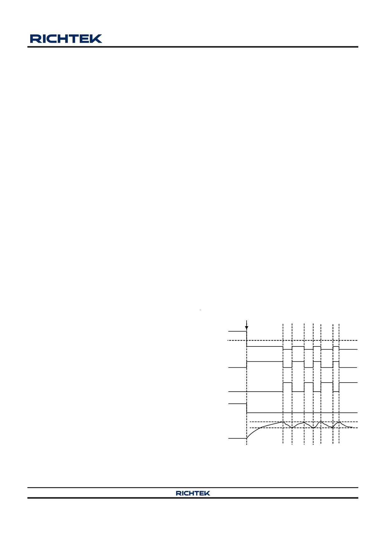
Thermal Shutdown
Thermal protection limits power dissipation in the
RT9712A/B/C/D. When the operation junction temperature
exceeds 120°C (typ.), the OTP circuit starts the thermal
shutdown function and turns the pass element off. The
pass element turns on again after the junction temperature
cools to 80°C. The IC lowers its OTP trip level from 120°C
to 100°C when output short circuit occurs (VOUT < 1V) as
shown in Figure 2.
VOUT Short to GND
1V
VOUT
IOUT
Thermal
Shutdown
OTP Trip
120 °C
Point
100 °C
100 °C
IC Temperature
80 °C
Figure 2. Short Circuit Thermal Folded Back Protection
when Output Short Circuit Occurs (Patent)
Copyright ©2012 Richtek Technology Corporation. All rights reserved.
DS9712-04 November 2012
is a registered trademark of Richtek Technology Corporation.
www.richtek.com
11
Share Link: 