RH1021C Просмотр технического описания (PDF) - Linear Technology
Номер в каталоге
Компоненты Описание
производитель
RH1021C Datasheet PDF : 2 Pages
| |||
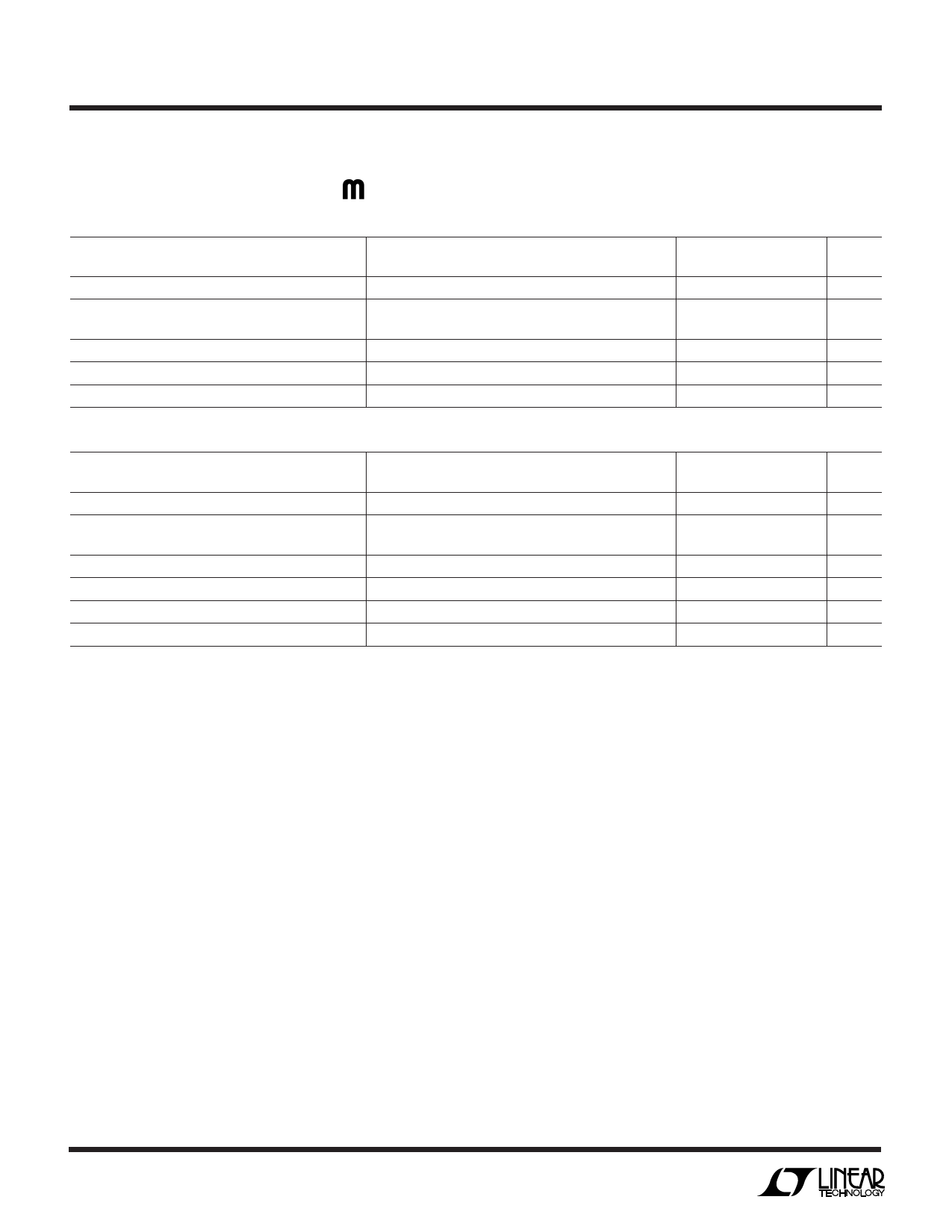
DICE SPECIFICATION
RH1021C
W
DICE ELECTRICAL TEST LI ITS
VS = 10V, IOUT = 0, TA = 25°C unless otherwise noted.
PARAMETER
Output Voltage (Note 1)
Line Regulation (Note 2)
Load Regulation (Sourcing Current)
Load Regulation (Sinking Current)
Supply Current
CONDITIONS
RH1021C-5
7.2V ≤ VIN ≤ 10V
10V ≤ VIN ≤ 40V
0 ≤ IOUT ≤ 10mA (Note 2)
0 ≤ IOUT ≤ 10mA (Note 2)
RH1021C-5
MIN
MAX
4.9975
5.0025
12
6
440
440
1.2
UNITS
V
ppm/V
ppm/V
ppm/mA
ppm/mA
mA
VS = 15V, IOUT = 0, TA = 25°C unless otherwise noted.
PARAMETER
CONDITIONS
RH1021C-10
MIN
MAX
UNITS
Output Voltage (Note 1)
RH1021C-10
9.995
10.005
V
Line Regulation (Note 2)
Load Regulation (Sourcing Current)
Load Regulation (Shunt Mode)
Supply Current (Series Mode)
11.5V ≤ VIN ≤ 14.5V
14.5V ≤ VIN ≤ 40V
0 ≤ IOUT ≤ 10mA (Note 2)
1.7mA ≤ ISHUNT ≤ 10mA (Notes 2, 3)
15
ppm/V
3
ppm/V
220 ppm/mA
220 ppm/mA
1.7
mA
Minimum Current (Shunt Mode)
VIN is Open
1.5
mA
Note 1: Output voltage is measured immediately after turn-on. Changes
due to chip warm-up are typically less than 0.005%.
Note 2: Line and load regulation are measured on a pulse basis. Output
changes due to die temperature change must be taken into account
separately.
Note 3: Shunt mode regulation is measured with the input open. With the
input connected, shunt mode current can be reduced to 0mA. Load
regulation will remain the same.
Rad Hard die require special handling as compared to standard IC
chips.
Rad Hard die are susceptible to surface damage because there is no
silicon nitride passivation as on standard die. Silicon nitride protects
the die surface from scratches by its hard and dense properties. The
passivation on Rad Hard die is silicon dioxide that is much “softer”
than silicon nitride.
LTC recommends that die handling be performed with extreme care so
as to protect the die surface from scratches. If the need arises to move
the die around from the chip tray, use a Teflon-tipped vacuum wand.
This wand can be made by pushing a small diameter Teflon tubing
onto the tip of a steel-tipped wand. The inside diameter of the Teflon
tip should match the die size for efficient pickup. The tip of the Teflon
should be cut square and flat to ensure good vacuum to die surface.
Ensure the Teflon tip remains clean from debris by inspecting under
stereoscope.
During die attach, care must be exercised to ensure no tweezers touch
the top of the die.
Wafer level testing is performed per the indicated specifications for dice. Considerable differences in performance can often be observed for dice versus
packaged units due to the influences of packaging and assembly on certain devices and/or parameters. Please consult factory for more information on
dice performance and lot qualifications via lot sampling test procedures.
Dice data sheet subject to change. Please consult factory for current revision in production.
I.D.No. 66-13-1021
2
Linear Technology Corporation
1630 McCarthy Blvd., Milpitas, CA 95035-7417
(408)432-1900 ● FAX:(408)434-0507 ● www.linear-tech.com
rh1021c LT/LT 1099 50 • PRINTED IN USA
© LINEAR TECHNOLOGY CORPORATION 1999
Share Link: 