ADM1020AR-REEL7 Просмотр технического описания (PDF) - Analog Devices
Номер в каталоге
Компоненты Описание
производитель
ADM1020AR-REEL7 Datasheet PDF : 12 Pages
| |||
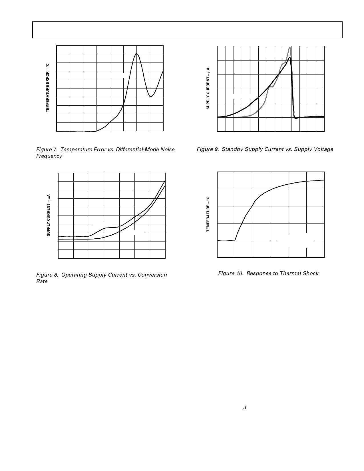
10
9
8
7
10mV SQ. WAVE
6
5
4
3
2
1
0
50 500 5k 50k 100k 500k 5M 25M 50M
FREQUENCY – Hz
Figure 7. Temperature Error vs. Differential-Mode Noise
Frequency
ADM1020
100
ADDX = HI-Z
80
60
40
ADDX = GND
20
0
–20
0 1.1 1.3 1.5 1.7 1.9 2.1 2.3 2.5 2.7 2.9 3.5 4.5
SUPPLY VOLTAGE – Volts
Figure 9. Standby Supply Current vs. Supply Voltage
200
180
160
140
120
100
80
VCC = +5V
60
VCC = +3.3V
40
20
0
0.0625 0.125 0.25
0.5
1
2
4
8
CONVERSION RATE – Hz
Figure 8. Operating Supply Current vs. Conversion
Rate
125
100
75
50
IMMERSED
25
IN +115؇C
FLUORINERT BATH
0
T=0
T=2
T=4
T=6
T=8
T = 10
TIME – Sec
Figure 10. Response to Thermal Shock
FUNCTIONAL DESCRIPTION
The ADM1020 contains a two-channel A-to-D converter with
special input-signal conditioning to enable operation with
remote and on-chip diode temperature sensors. When the
ADM1020 is operating normally, the A-to-D converter operates
in a free-running mode. The analog input multiplexer alternately
selects either the on-chip temperature sensor to measure its local
temperature, or the remote temperature sensor. These signals
are digitized by the ADC and the results stored in the local and
remote temperature value registers as 8-bit, twos complement
words.
The measurement results are compared with local and remote,
high and low temperature limits, stored in four on-chip regis-
ters. Out of limit comparisons generate flags that are stored in
the Status Register, and one or more out-of-limit results will
cause the ALERT output to pull low.
The limit registers can be programmed, and the device con-
trolled and configured, via the serial System Management Bus
(SMBus). The contents of any register can also be read back via
the SMBus.
Control and configuration functions consist of:
– switching the device between normal operation and standby
mode.
– masking or enabling the ALERT output.
– selecting the conversion rate.
MEASUREMENT METHOD
A simple method of measuring temperature is to exploit the
negative temperature coefficient of a diode, or the base-emitter
voltage of a transistor, operated at constant current. Unfortu-
nately, this technique requires calibration to null out the effect
of the absolute value of VBE, which varies from device to device.
The technique used in the ADM1020 is to measure the change
in VBE when the device is operated at two different currents.
This is given by:
∆VBE = KT/q × ln (N)
where:
K is Boltzmann’s constant.
q is charge on the electron (1.6 × 10⁻¹⁹ Coulombs).
T is absolute temperature in Kelvins.
N is ratio of the two currents.
REV. 0
–5–
Share Link: 