PM300CLA060 Просмотр технического описания (PDF) - Mitsumi
Номер в каталоге
Компоненты Описание
производитель
PM300CLA060 Datasheet PDF : 8 Pages
| |||
MITSUBISHI <INTELLIGENT POWER MODULES>
PM300CLA060
FLAT-BASE TYPE
INSULATED PACKAGE
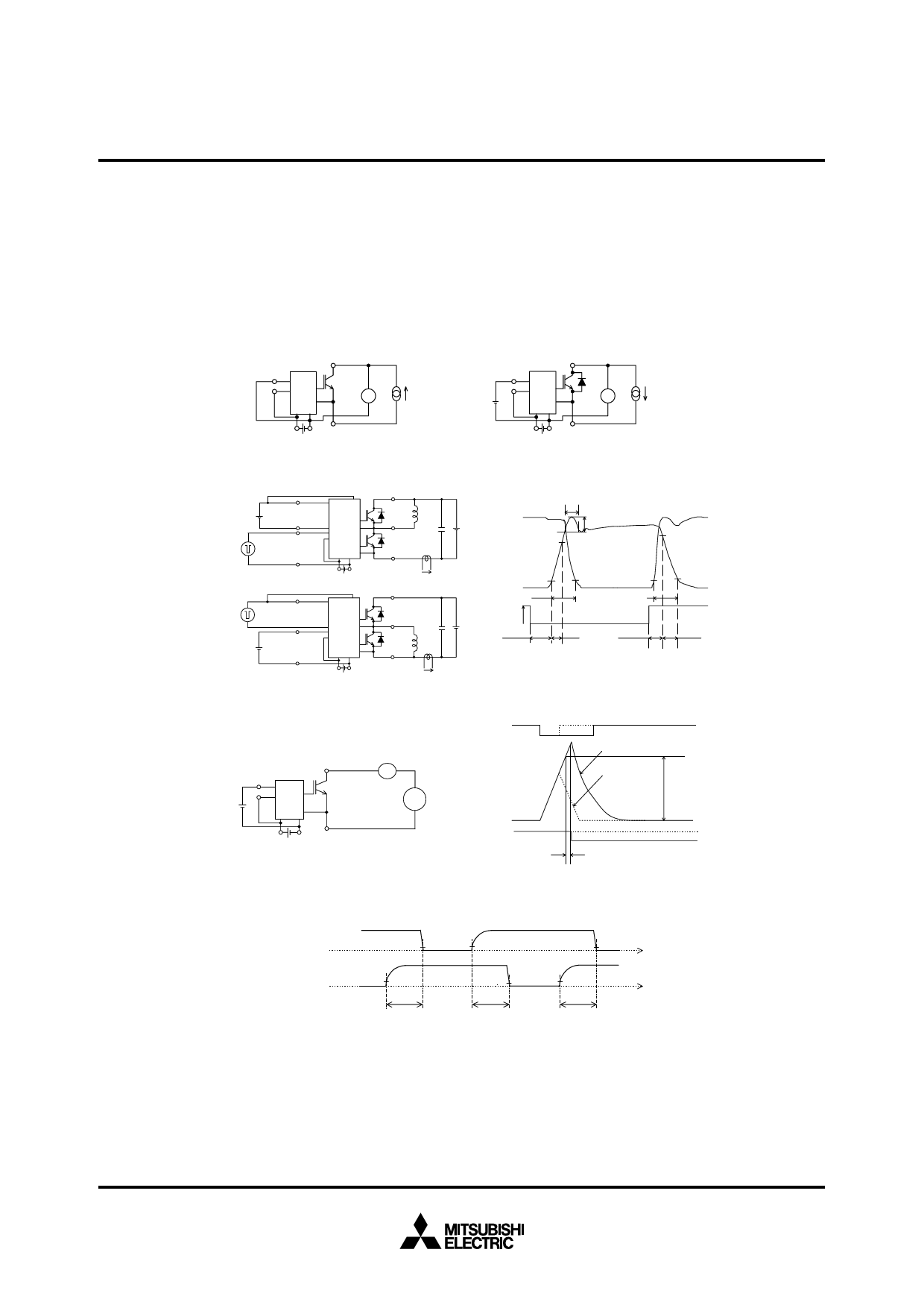
PRECAUTIONS FOR TESTING
1. Before appling any control supply voltage (VD), the input terminals should be pulled up by resistores, etc. to their corre-
sponding supply voltage and each input signal should be kept off state.
After this, the specified ON and OFF level setting for each input signal should be done.
2. When performing “SC” tests, the turn-off surge voltage spike at the corresponding protection operation should not be al-
lowed to rise above VCES rating of the device.
(These test should not be done by using a curve tracer or its equivalent.)
P, (U,V,W)
IN
Fo
VCIN
(0V)
V
Ic
VD (all) U,V,W, (N)
Fig. 1 VCE(sat) Test
a) Lower Arm Switching
Fo
VCIN
Signal input
(15V) (Upper Arm)
Signal input Fo
VCIN
(Lower Arm)
P
U,V,W
CS
b) Upper Arm Switching
VD (all)
Fo
VCIN
Signal input
(Upper Arm)
VCIN
(15V)
Fo
Signal input
(Lower Arm)
N
Ic
P
U,V,W
CS
N
VD (all)
Ic
Fig. 3 Switching time and SC test circuit
VCIN
(15V)
P, (U,V,W)
IN
Fo
V
–Ic
VD (all) U,V,W, (N)
Fig. 2 VEC Test
trr
VCE
Irr
Ic
Vcc
90%
90%
10%
10%
10%
tc(on)
tc(off)
VCIN
Vcc
td(on)
tr
td(off)
10%
tf
(ton= td(on) + tr)
(toff= td(off) + tf)
Fig. 4 Switching time test waveform
VCIN
(15V)
P, (U,V,W)
A
IN
Fo
Pulse VCE
U,V,W, (N)
VD (all)
Fig. 5 ICES Test
VCIN
Ic
Short Circuit Current
Constant Current
SC
Fo
toff(SC)
Fig. 6 SC test waveform
IPM’ input signal VCIN
(Upper Arm)
0V
1.5V
2V
1.5V
t
IPM’ input signal VCIN
(Lower Arm)
0V
2V
tdead
1.5V
2V
t
tdead
tdead
1.5V: Input on threshold voltage Vth(on) typical value, 2V: Input off threshold voltage Vth(off) typical value
Fig. 7 Dead time measurement point example
May 2005
Share Link: 