HT48C06 Просмотр технического описания (PDF) - Holtek Semiconductor
Номер в каталоге
Компоненты Описание
производитель
HT48C06 Datasheet PDF : 38 Pages
| |||
HT48R05A-1/HT48C05/HT48R06A-1/HT48C06
Pin Assignment
PA3 1
PA2 2
PA1 3
PA0 4
P B 0 /B Z 5
VSS
6
P C 0 /IN T 7
P C 1 /T M R
8
16 P A 4
15 P A 5
14 P A 6
13 P A 7
12 O S C 2
11 O S C 1
10 V D D
9 RES
H T 4 8 R 0 5 A -1 /H T 4 8 C 0 5
H T 4 8 R 0 6 A -1 /H T 4 8 C 0 6
1 6 S S O P -A
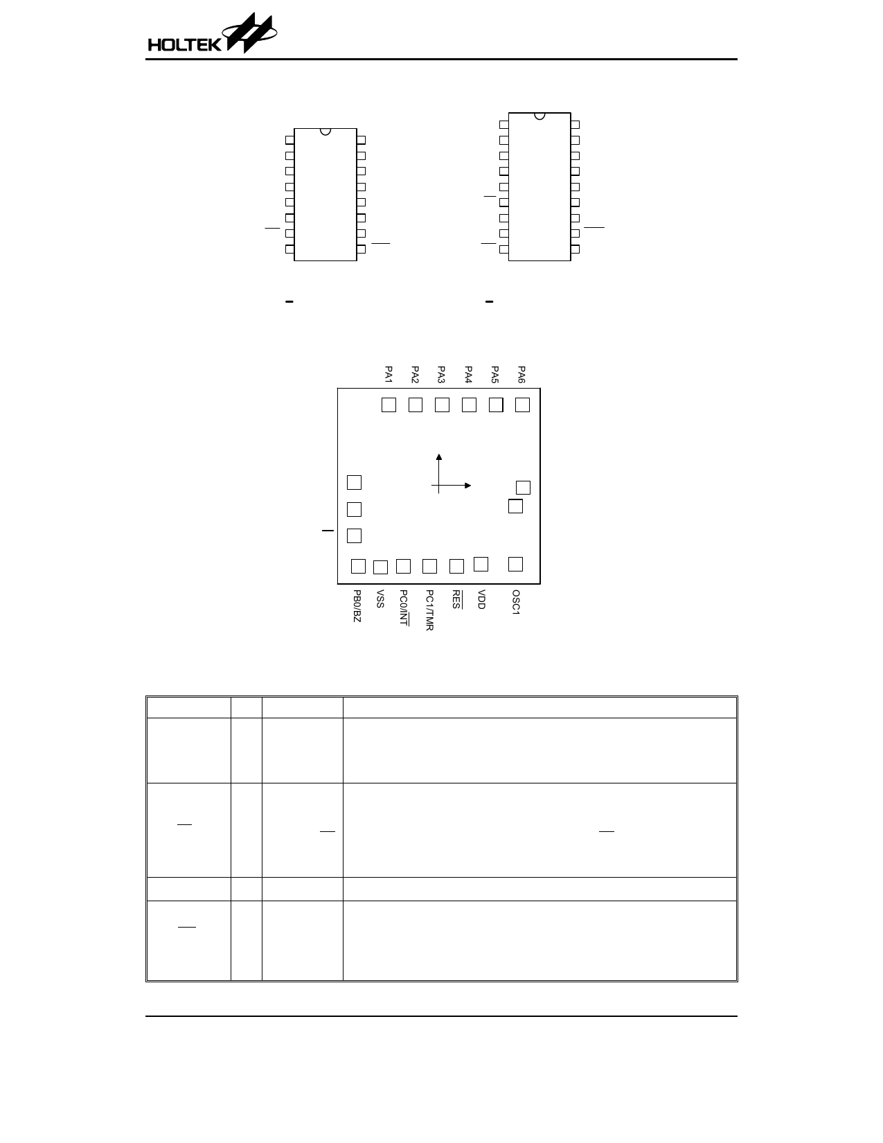
Pad Assignment
PA3 1
PA2 2
PA1 3
PA0 4
PB2 5
P B 1 /B Z 6
P B 0 /B Z 7
VSS 8
P C 0 /IN T 9
18 P A 4
17 P A 5
16 P A 6
15 P A 7
14 O S C 2
13 O S C 1
12 V D D
11 R E S
1 0 P C 1 /T M R
H T 4 8 R 0 5 A -1 /H T 4 8 C 0 5
H T 4 8 R 0 6 A -1 /H T 4 8 C 0 6
1 8 D IP -A /S O P -A
18 17 16 15 14 13
PA0 1
PB2 2
P B 1 /B Z
3
456
(0 ,0 )
7
8
9
12 P A 7
11
O SC2
10
* The IC substrate should be connected to VSS in the PCB layout artwork.
Pad Description
Pad Name I/O Options
Description
PA0~PA7
Bidirectional 8-bit input/output port. Each bit can be configured as wake-up
I/O
Pull-high* input by options. Software instructions determine the CMOS output or
Wake-up Schmitt trigger input with a pull-high resistor (determined by pull-high op-
tions).
PB0/BZ
PB1/BZ
PB2
Bidirectional 3-bit input/output port. Software instructions determine the
CMOS output or Schmitt trigger input with a pull-high resistor (determined by
I/O
Pull-high* pull-high options).
I/O or BZ/BZ The PB0 and PB1 are pin-shared with the BZ and BZ, respectively. Once the
PB0 and PB1 are selected as buzzer driving outputs, the output signals come
from an internal PFD generator (shared with a timer/event counter).
VSS
¾
¾
Negative power supply, ground
PC0/INT
PC1/TMR
Bidirectional I/O lines. Software instructions determine the CMOS output or
Schmitt trigger input with a pull-high resistor (determined by pull-high op-
I/O Pull-high* tions). The external interrupt and timer input are pin-shared with the PC0 and
PC1, respectively. The external interrupt input is activated on a high to low
transition.
Rev. 1.10
2
June 9, 2004
Share Link: 