HT48RA0A Просмотр технического описания (PDF) - Holtek Semiconductor
Номер в каталоге
Компоненты Описание
производитель
HT48RA0A Datasheet PDF : 31 Pages
| |||
HT48RA0A
D.C. Characteristics
Ta=25°C
Symbol
Parameter
Test Conditions
VDD
Conditions
VDD
Operating Voltage
¾ LVR disabled
IDD
Operating Current
3V No load, fSYS=4MHz
ISTB
Standby Current
3V No load, system HALT
VIL1
Input Low Voltage for I/O Ports 3V
¾
VIH1
Input High Voltage for I/O Ports 3V
¾
VIL2
Input Low Voltage (RES)
3V
¾
VIH2
Input High Voltage (RES)
3V
¾
IOL
I/O Ports Sink Current
3V VOL=0.1VDD
IOH
PC0/REM Output Source Current 3V VOH=0.9VDD
RPH1
Pull-high Resistance of PA Port,
PB0~PB1 and RES
3V
¾
RPH2
Pull-high Resistance of PB2~PB7 3V
¾
Min.
2.2
¾
¾
0
0.7VDD
0
0.9VDD
1.5
-1
¾
¾
Typ.
¾
0.7
¾
¾
¾
¾
¾
2.5
-1.5
60
60
Max.
3.6
1.5
1
0.3VDD
VDD
0.4VDD
VDD
¾
¾
¾
¾
Unit
V
mA
mA
V
V
V
V
mA
mA
kW
kW
A.C. Characteristics
Ta=25°C
Symbol
Parameter
fSYS
System Clock
tRES
External Reset Low Pulse Width
tSST
System Start-up Timer Period
Test Conditions
VDD
Conditions
Min. Typ. Max. Unit
3V
¾
400 ¾ 4000 kHz
¾
¾
1 ¾ ¾ ms
¾ Power-up or wake-up from HALT ¾ 1024 ¾ tSYS
Note: tSYS=1/fSYS
Functional Description
Execution Flow
The HT48RA0A system clock can be derived from a
crystal/ceramic resonator oscillator. It is internally di-
vided into four non-overlapping clocks. One instruction
cycle consists of four system clock cycles.
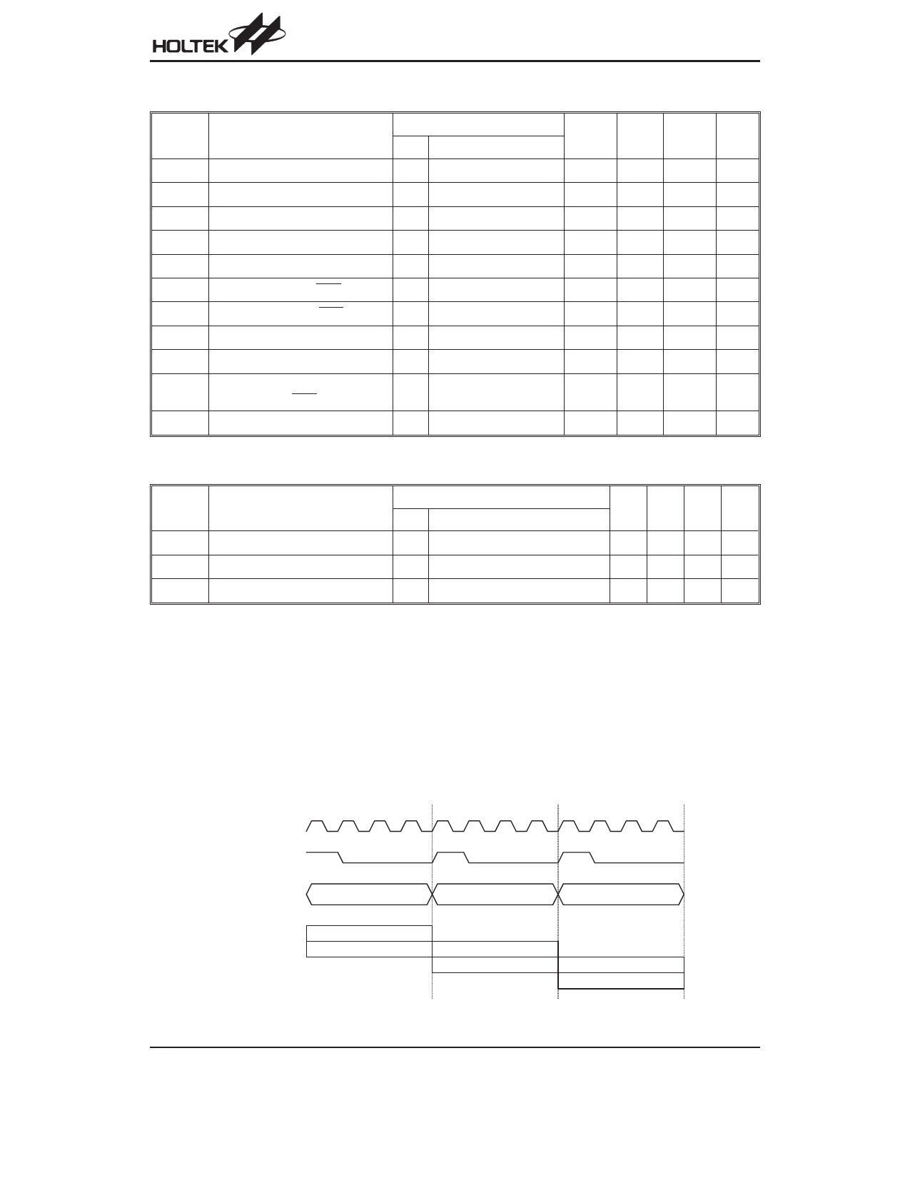
T1 T2 T3 T4 T1
S y s te m C lo c k
In s tr u c tio n C y c le
Instruction fetching and execution are pipelined in such
a way that a fetch takes one instruction cycle while de-
coding and execution takes the next instruction cycle.
However, the pipelining scheme causes each instruc-
tion to effectively execute within one cycle. If an instruc-
tion changes the program counter, two cycles are
required to complete the instruction.
T2 T3 T4 T1 T2 T3 T4
PC
PC
PC +1
PC +2
F e tc h IN S T (P C )
E x e c u te IN S T (P C -1 )
F e tc h IN S T (P C + 1 )
E x e c u te IN S T (P C )
F e tc h IN S T (P C + 2 )
E x e c u te IN S T (P C + 1 )
Execution flow
Rev. 1.70
3
July 16, 2003
Share Link: 