PCK210 Просмотр технического описания (PDF) - Philips Electronics
Номер в каталоге
Компоненты Описание
производитель
PCK210 Datasheet PDF : 10 Pages
| |||
Philips Semiconductors
Low voltage dual 1:5 differential
ECL/PECL clock driver
Product data
PCK210
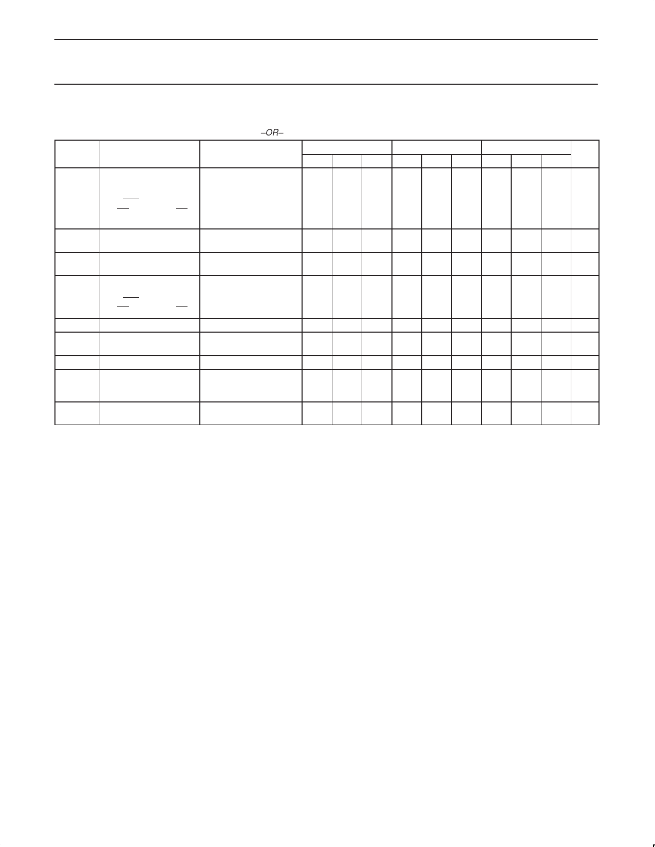
AC CHARACTERISTICS — PECL input
Vsupply: VCC = VCCO = 2.25 V to 3.80 V; VEE = 0.0 V –OR–
SYMBOL
PARAMETER
CONDITIONS
VCC = VCCO = 0.0 V; VEE = –2.25 V to –3.80 V.
–40 °C
+25 °C
MIN TYP MAX MIN TYP MAX
Nominal (single input
Differential propagation condition)
tPD
delay
CLK,CLK to all
VPP = 0.650 V,
VCMR = VCC – 0.800 V
270
–
420 300
–
450
Q0,Q0 through Q4,Q4 Applies to 500 MHz
reference. (Note 1)
tSK(part) Part-to-part skew
Single input condition
(Note 1)
–
– 110 –
– 110
tSK(output)
Output-to-output skew
for given part
Single input condition
(Note 1)
–
15 50
–
15 50
Differential propagation
tPD
delay
CLK,CLK to all
All input conditions
(Note 1)
Q0,Q0 through Q4,Q4
220 – 520 250 – 550
tSK(part) Part-to-part skew
tSK(output)
Output-to-output skew
for given part
(Note 1)
(Note 1)
–
– 160 –
– 160
–
15 50
–
15 50
tjitter
fMAX
Cyle-to-cycle jitter
Maximum frequency
Functional to 1.5 GHz
Timing specifications
apply up to 1.0 GHz
–
–
1
–
–
1
–
– 1500 –
– 1500
tr, tf
Output rise and fall
times (20%, 80%)
(Note 1)
100 – 320 100 – 320
+85 °C
UNIT
MIN TYP MAX
380 – 530 ps
–
– 110 ps
–
15 50 ps
320 – 620 ps
–
– 160 ps
–
15 50 ps
–
–
1 ns
–
– 1500 MHz
100 – 320 ps
NOTE:
1. For operation with 2.5 V supply, the output termination is 50 Ω to VEE.
For operation at 3.3 V supply, the output termination is 50 Ω to VCC – 2 V.
2004 Apr 23
6
Share Link: 