PCF8533 Просмотр технического описания (PDF) - Philips Electronics
Номер в каталоге
Компоненты Описание
производитель
PCF8533 Datasheet PDF : 36 Pages
| |||
Philips Semiconductors
Universal LCD driver for low multiplex rates
Product specification
PCF8533
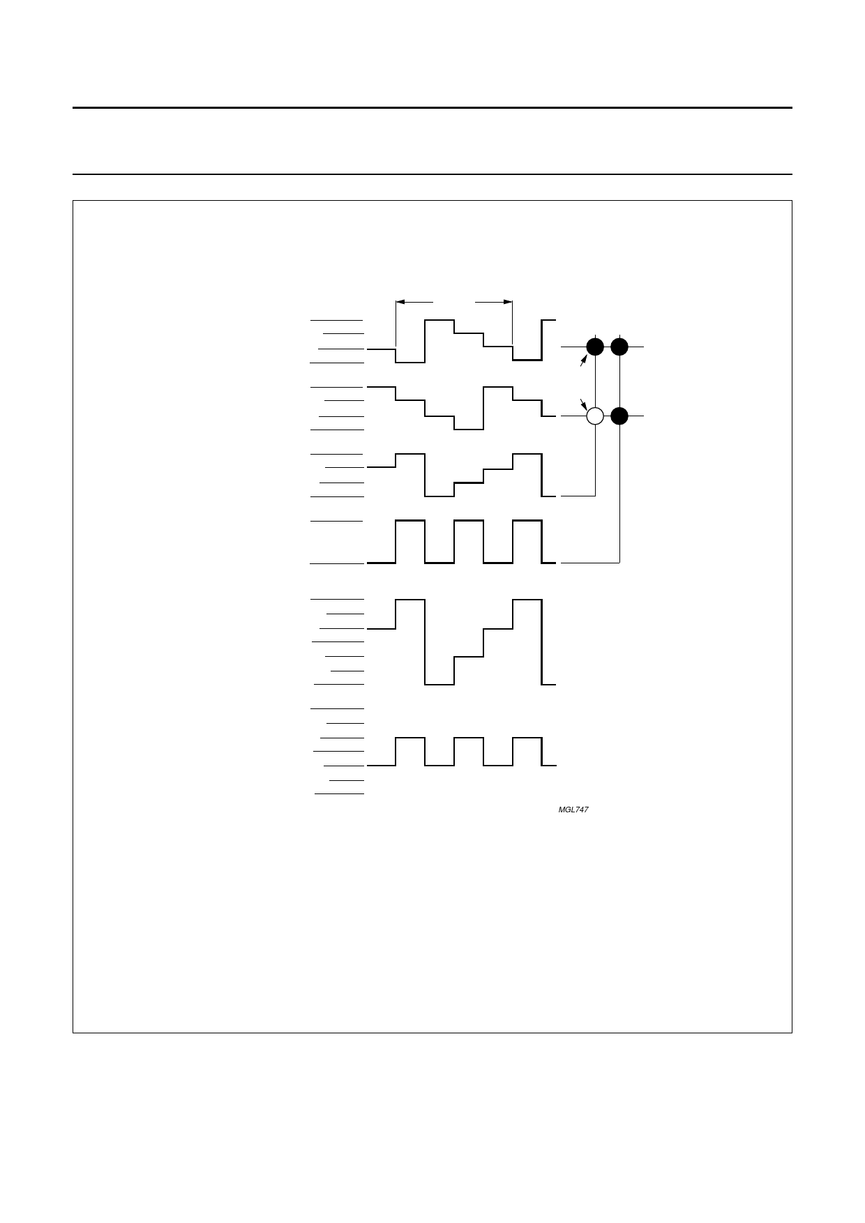
handbook, full pagewidth
BP0
BP1
Sn
Sn + 1
state 1
state 2
VLCD
2VLCD/3
VLCD/3
VSS
VLCD
2VLCD/3
VLCD/3
VSS
VLCD
2VLCD/3
VLCD/3
VSS
VLCD
2VLCD/3
VLCD/3
VSS
VLCD
2VLCD/3
VLCD/3
0V
−VLCD/3
−2VLCD/3
−VLCD
VLCD
2VLCD/3
VLCD/3
0V
−VLCD/3
−2VLCD/3
−VLCD
Tframe
LCD segments
state 1
state 2
(a) Waveforms at driver.
(b) Resultant waveforms
at LCD segment.
MGL747
Vstate1(t) = Vsn(t) − VBP0(t).
Von(rms) = 0.745VLCD.
Vstate2(t) = Vsn(t) − VBP1(t).
Voff(rms) = 0.333VLCD.
Fig.5 Waveforms for the 1 : 2 multiplex drive mode with 1⁄3bias.
6.4.3 1 : 3 MULTIPLEX DRIVE MODE
When three backplanes are provided in the LCD, the 1 : 3 multiplex drive mode applies, as shown in Fig.6.
1999 Jul 30
10
Share Link: 