NTE926 Просмотр технического описания (PDF) - NTE Electronics
Номер в каталоге
Компоненты Описание
производитель
NTE926 Datasheet PDF : 2 Pages
| |||
DC & AC Electrical Characteristics: (TA = +25°C, VCC = +5V, unless otherwise specified)
Parameter
Symbol
Test Conditions
Min Typ Max Unit
Supply Voltage
Supply Current
Timing Accuracy (t = RC)
VCC
4.5 – 16
V
ICC VCC = Reset = 15V
– 16 36
mA
R = 2kΩ to 100kΩ, C = 1µF
Initial Accuracy
– ±2 5
%
Drift with Temperature
– 30 150 ppm/°C
Drift with Supply Voltage
– 0.1 0.9 %/V
Trigger Voltage
Trigger Current
VCC = 15V, Note 1
Trigger = 0V
0.8 – 2.4
V
–
5 100
µA
Reset Voltage
Note 2
0.8 – 2.4
V
Reset Current
Reset
– 50 500
µA
Threshold Voltage
Threshold Leakage
– 0.63 –
– 15 –
x VCC
nA
Output Voltage
VOUT IL = 10mA, Note 3
– 0.1 0.4
V
– 1.0 2.0
V
Output Leakage
– 10 500
nA
Propagation Delay
Rise Time of Output
Fall Time of Output
tPD
tR IL = 100mA
tF
IL = 100mA
– 1.0 –
µS
– 100 –
nS
– 100 –
nS
Note 1. The trigger functions only on the falling edge of the trigger pulse only after previously being
high. After reset, the trigger must be brought high and then low to implement triggering.
Note 2. For reset below 0.8V, outputs set low and trigger inhibited. For reset above 2.4V, trigger
enabled.
Note 3. The NTE926 output structure is open–collector which requires a pull–up resistor to VCC to
sink current. The output is normally low sinking current.
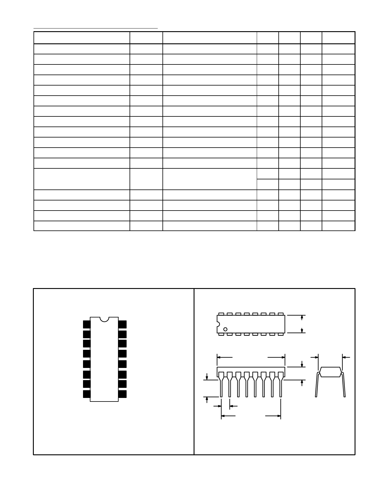
Pin Connection Diagram
Output A 1
Timing A 2
Trigger A 3
Control Voltage 4
VCC 5
Trigger B 6
Timing B 7
Output B 8
16 Output D
15 Timing D
14 Trigger D
13 Reset
12 GND
11 Trigger C
10 Timing C
9 Output C
16
1
.245
(6.22)
Min
.785 (19.9)
Max
.100 (2.54)
.700 (17.7)
9
.260 (6.6) Max
8
.200 (5.08)
Max
.300
(7.62)
Share Link: 