HI5746KCA Просмотр технического описания (PDF) - Intersil
Номер в каталоге
Компоненты Описание
производитель
HI5746KCA Datasheet PDF : 16 Pages
| |||
Typical Performance Curves (Continued)
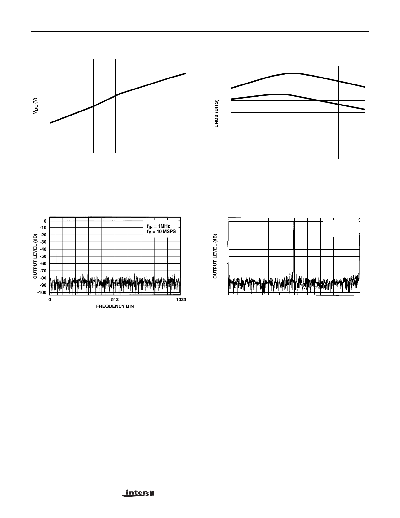
3.30
HI5746
9.0
3.20
8.8
3.10
3.00
-40
-20
0
20
40
60
80
TEMPERATURE (oC)
FIGURE 21. DC BIAS VOLTAGE (VDC) vs TEMPERATURE
8.6
8.4
8.2
-40
-20
0
20
40
60
80
TEMPERATURE (oC)
FIGURE 22. EFFECTIVE NUMBER OF BITS F(ENOB) vs
TEMPERATURE
FIGURE 23. 2048 POINT FFT PLOT
Detailed Description
Theory of Operation
The HI5746 is a 10-bit fully differential sampling pipeline A/D
converter with digital error correction logic. Figure 25 depicts
the circuit for the front end differential-in-differential-out sample-
and-hold (S/H). The switches are controlled by an internal
sampling clock which is a non-overlapping two phase signal, φ1
and φ2, derived from the master sampling clock. During the
sampling phase, φ1, the input signal is applied to the sampling
capacitors, CS. At the same time the holding capacitors, CH,
are discharged to analog ground. At the falling edge of φ1 the
input signal is sampled on the bottom plates of the sampling
capacitors. In the next clock phase, φ2, the two bottom plates of
the sampling capacitors are connected together and the
holding capacitors are switched to the op amp output nodes.
The charge then redistributes between CS and CH completing
one sample-and-hold cycle. The front end sample-and-hold
11
0
-10
-20
-30
-40
-50
-60
-70
-80
-90
-100
0
fIN = 10MHz
fS = 40 MSPS
512
FREQUENCY BIN
1023
FIGURE 24. 2048 POINT FFT SPECTRAL PLOT
output is a fully-differential, sampled-data representation of the
analog input. The circuit not only performs the sample-and-hold
function but will also convert a single-ended input to a fully-
differential output for the converter core. During the sampling
phase, the VIN pins see only the on-resistance of a switch and
CS. The relatively small values of these components result in a
typical full power input bandwidth of 250MHz for the converter.
Share Link: 