NJU26100 Просмотр технического описания (PDF) - Japan Radio Corporation
Номер в каталоге
Компоненты Описание
производитель
NJU26100 Datasheet PDF : 17 Pages
| |||
NJU26100 Series
4. Audio Interface
The serial audio interface carries audio data to and from the NJU26100 Series. Industry standard serial data
formats of I2S, MSB-first left-justified or MSB-first right-justified are supported. These serial audio formats define a
pair of digital audio signals (stereo audio) on each data line. Two clock lines, BCK (bit clock) and LR (left/right word
clock) establish timing for serial data transfers.
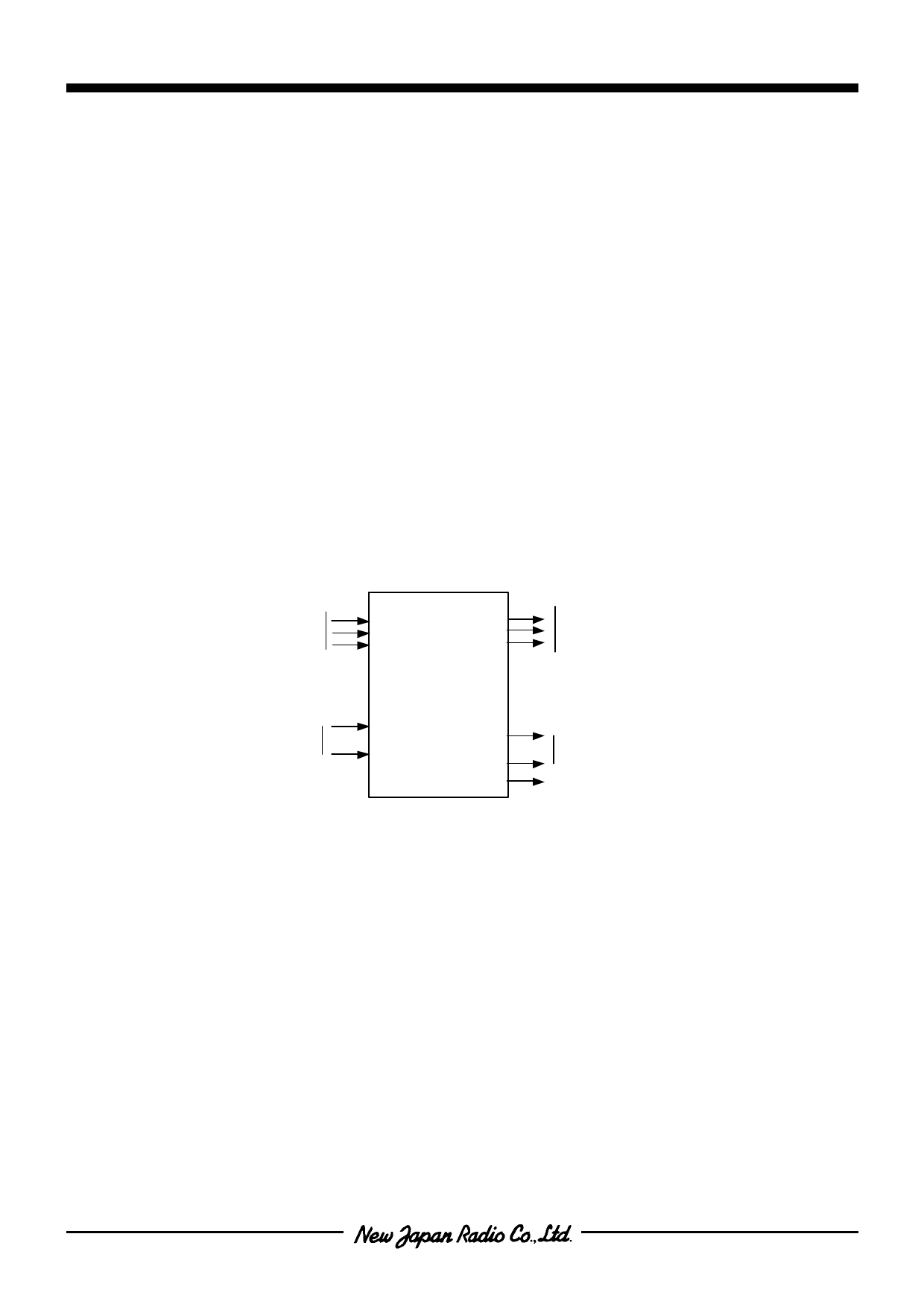
The NJU26100 Series serial audio interface includes three data input lines, SDI0, SDI1 and SDI2, and three data
output lines, SDO0, SDO1 and SDO2, as shown in the figure below. The input serial data is selected by the
firmaware command. The number of these serial audio interfaces depends on the DSP function. Check the each
data sheet.
The NJU26100 Series has a pair of left/right clock lines (LRI and LRO) and a pair of bit clock lines (BCKI and
BCKO). Clock inputs BCKI and LRI are used to accept timing signals from an external device when the NJU26100
Series is operating in SLAVE clock mode.
The BCKO, LRO and MCK, system clock output, are provided for delta-sigma A/D and D/A converters when the
NJU26100 Series operates in MASTER mode. In SLAVE mode, the output of BCKO and LRO are the buffered
output of BCKI and LRI. The output of MCK is fixed to Low level in SLAVE mode.
Serial
Data
Inputs
SDI0
SDI1
SDI2
SDO0
SDO1
SDO2
Serial
Data
Outputs
NJU26100
Serial
Clock
Inputs
BCKI
LRI
BCKO
LRO
MCK
Serial
Clock
Outputs
System clock for
A/D, D/A converters
(DSP MASTER mode only)
Fig. 4-1 Serial Audio Interface
4.1 Audio Data Format
The NJU26100 Series can exchange data using any of three industry-standard digital audio data formats: I2S,
MSB-first Left-justified, or MSB-first Right-justified.
The three serial formats differ primarily in the placement of the audio data word relative to the LR clock.
Left-justified format places the most-significant data bit (MSB) as the first bit after an LR transition. I2S format places
the most-significant data bit (MSB) as the second bit after an LR transition (one bit delay relative to left-justified
format). Right-justified format places the least-significant data bit (LSB) as the last bit before an LR transition.
Clock LR (LRI, LRO) marks data word boundaries and clock BCK (BCKI, BCKO) clocks the transfer of serial
data bits. One period of LR defines a complete stereo audio sample and thus the rate of LR equals the audio
sample rate (Fs). All formats transmit the stereo sample left channel first. Note that polarity of LR is opposite in I2S
format (LR:LOW = Left channel data) compared to Left-Justified or Right-Justified formats.
Ver.2005-02-24
-7-
Share Link: 