NCP1253 Просмотр технического описания (PDF) - ON Semiconductor
Номер в каталоге
Компоненты Описание
производитель
NCP1253 Datasheet PDF : 15 Pages
| |||
D2
1N4007
input
mains
D4
1N4007
NCP1253
R3
100k
D1
1N4007
D3
1N4007
Cbulk
22uF
Vcc
R2
100k
R1
200k
D6
1N4148
D5
1N4935
C1
4.7uF
C3
47uF
aux.
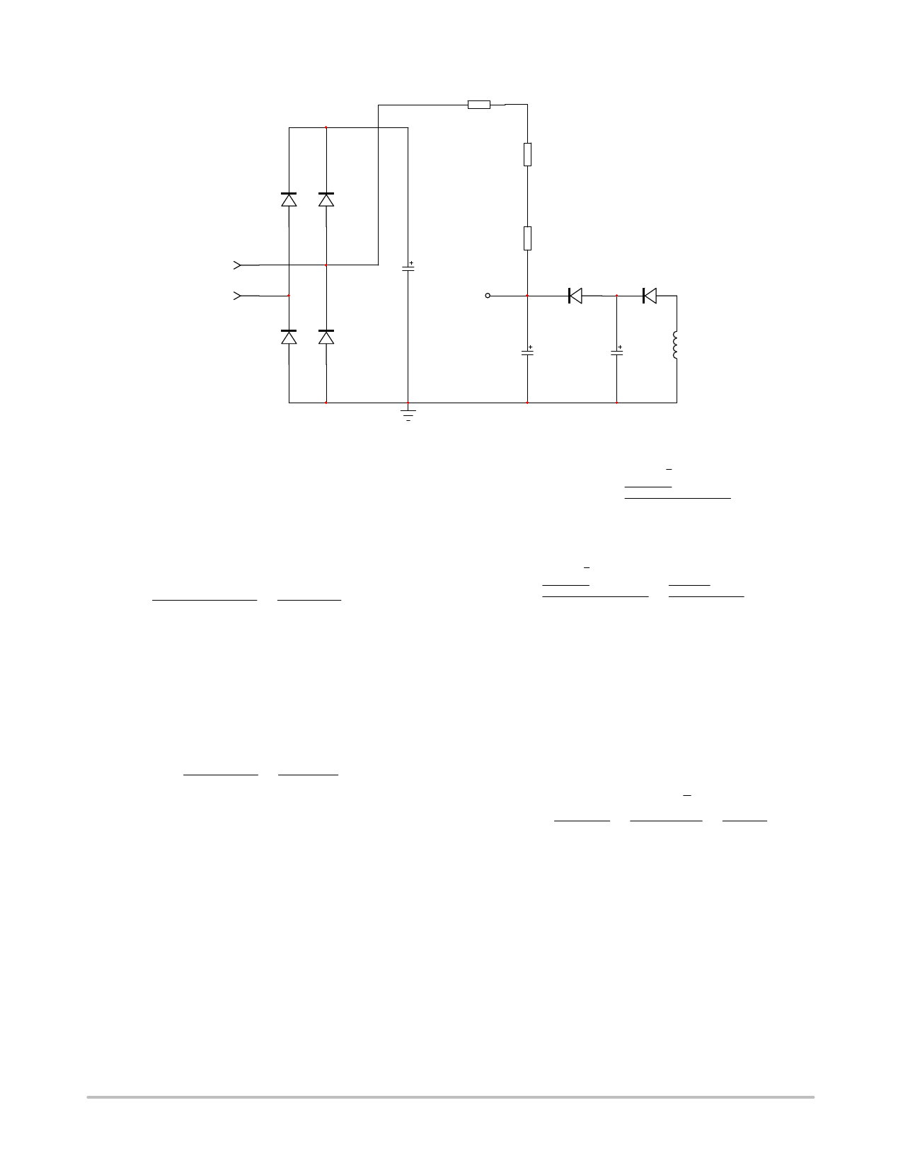
Figure 25. The Startup Resistor Can Be Connected to the Input Mains for Further Power Dissipation Reduction
The first step starts with the calculation of the needed VCC
capacitor which will supply the controller until the auxiliary
winding takes over. Experience shows that this time t1 can
be between 5 and 20 ms. Considering that we need at least
an energy reservoir for a t1 time of 10 ms, the Vcc capacitor
must be larger than:
CVCC
w
ICCt1
VCCon * VCCmin
w
3m
10m
w
3.3
(eq.
mF
1)
9
Let us select a 4.7 mF capacitor at first and experiments in
the laboratory will let us know if we were too optimistic for
t1. The VCC capacitor being known, we can now evaluate the
charging current we need to bring the Vcc voltage from 0 to
the VCCon of the IC, 18 V typical. This current has to be
selected to ensure a start−up at the lowest mains (85 V rms)
to be less than 3 s (2.5 s for design margin):
Icharge
w
VCCOnCVCC
2.5
w
18
4.7m
2.5
w
34
(eq. 2)
mA
If we account for the 15 mA that will flow inside the
controller, then the total charging current delivered by the
start−up resistor must be 49 mA. If we connect the start−up
network to the mains (half−wave connection then), we know
that the average current flowing into this start−up resistor
will be the smallest when VCC reaches the VCCon of the
controller:
ICVCC,min
+
Vac,rmsǸ2
p
*
VCCon
Rstart−up
(eq. 3)
To make sure this current is always greater than 49 mA, the
maximum value for Rstart−up can be extracted:
Rstart−up
v
Vac,rmsǸ2
p
*
VCCon
ICVCC,min
v
85
1.414
p
*
18
v
(eq. 4)
413 kW
49m
This calculation is purely theoretical, considering a
constant charging current. In reality, the take over time can
be shorter (or longer!) and it can lead to a reduction of the
Vcc capacitor. This brings a decrease in the charging current
and an increase of the start−up resistor, for the benefit of
standby power. Laboratory experiments on the prototype are
thus mandatory to fine tune the converter. If we chose the
400k resistor as suggested by Equation 4, the dissipated
power at high line amounts to:
ǒ Ǔ Vac,peak 2
PRstart,max + 4Rstart−up +
320
4
Ǹ2 2
+
105k
400k 1.6Meg
(eq. 5)
+ 66 mW
Now that the first VCC capacitor has been selected, we
must ensure that the self−supply does not disappear when in
no−load conditions. In this mode, the skip−cycle can be so
deep that refreshing pulses are likely to be widely spaced,
inducing a large ripple on the VCC capacitor. If this ripple is
too large, chances exist to touch the VCCmin and reset the
controller into a new start−up sequence. A solution is to
grow this capacitor but it will obviously be detrimental to the
start−up time. The option offered in Figure 25 elegantly
http://onsemi.com
11
Share Link: 