NCP1246 Просмотр технического описания (PDF) - ON Semiconductor
Номер в каталоге
Компоненты Описание
производитель
NCP1246 Datasheet PDF : 38 Pages
| |||
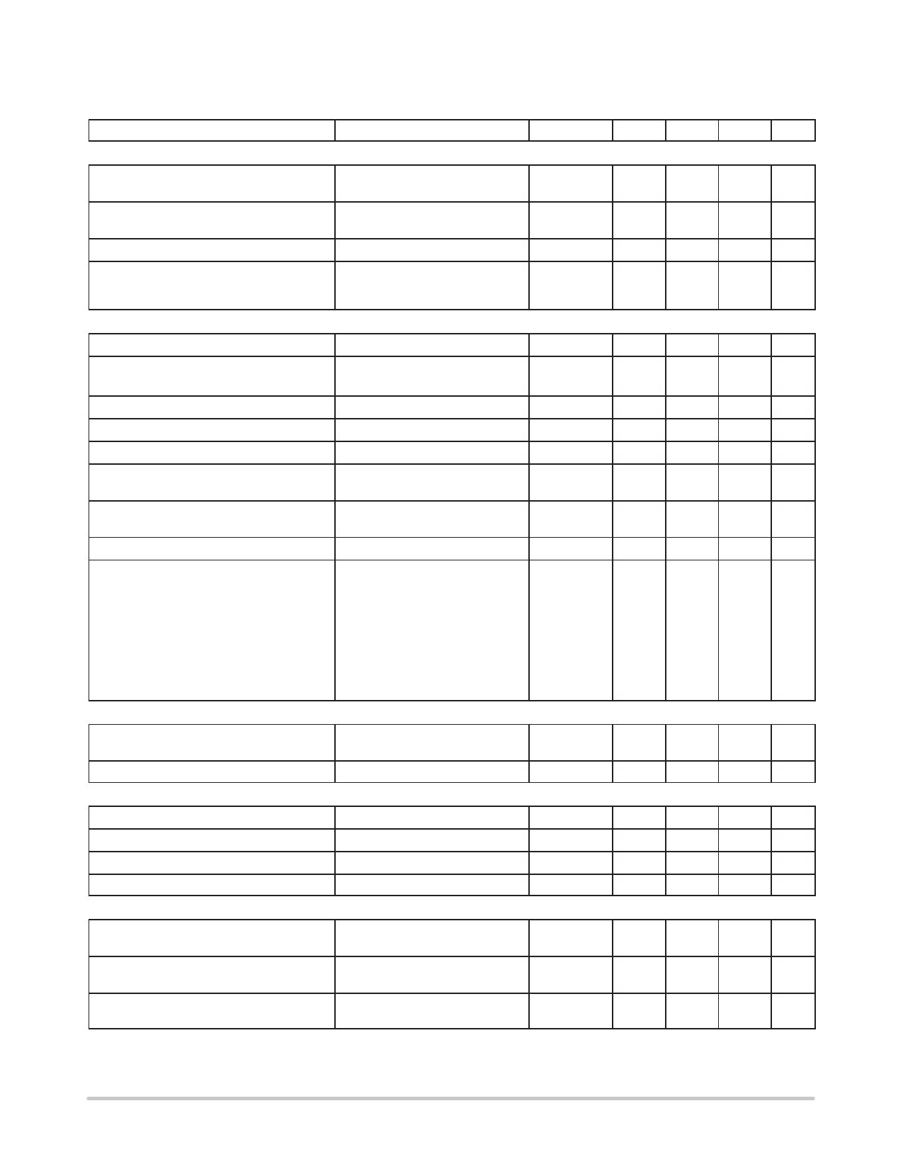
NCP1246
ELECTRICAL CHARACTERISTICS (For typical values TJ = 25°C, for min/max values TJ = ï40°C to +125°C, VHV = 125 V,
VCC = 11 V unless otherwise noted)
Characteristics
Test Condition
Symbol
Min
Typ
Max
HIGH VOLTAGE CURRENT SOURCE
Minimum voltage for current source
operation
VHV(min)
ï
30
40
Current flowing out of VCC pin
Offïstate leakage current
Offïmode HV supply current
SUPPLY
VCC = 0 V
VCC = VCC(on) ï 0.5 V
VHV = 500 V, VCC = 15 V
VHV = 141 V,
VHV = 325 V,
VCC loaded by 4.7 mF cap
Istart1
Istart2
Istart(off)
IHV(off)
0.2
0.5
0.8
5
8
11
10
25
50
ï
45
60
ï
50
70
HV current source regulation threshold
Turnïon threshold level, VCC going up
HV current source stop threshold
VCC(reg)
VCC(on)
8
11
ï
11.0
12.0
13.0
HV current source restart threshold
Turnïoff threshold
Overvoltage threshold
Blanking duration on VCC(off) and VCC(ovp)
detection
VCC(min)
9.5
10.5 11.5
VCC(off)
8.5
8.9
9.3
VCC(ovp)
25
26.5
28
tVCC(blank)
7
10
13
VCC decreasing level at which the internal
logic resets
VCC(reset)
4.8
7.0
7.7
VCC level for ISTART1 to ISTART2 transition
Internal current consumption (Note 6)
VCC(inhibit)
0.2
0.8
1.25
DRV open, VFB = 3 V, 65 kHz
ICC1
1.3
1.85
2.2
DRV open, VFB = 3 V, 100 kHz
ICC1
1.3
1.85
2.2
Cdrv = 1 nF, VFB = 3 V, 65 kHz
ICC2
Cdrv = 1 nF, VFB = 3 V, 100 kHz
ICC2
1.8
2.6
3.0
2.3
2.9
3.5
ICC3
Off mode (skip or before startïup)
ICC4
Fault mode (fault or latch)
0.67
0.9
1.13
0.3
0.6
0.9
BROWNïOUT
BrownïOut thresholds
Timer duration for line cycle dropïout
X2 DISCHARGE
VHV going up
VHV going down
VHV(start)
102
111
120
VHV(stop)
94
103
112
tHV
43
ï
86
Comparator hysteresis observed at HV pin
HV signal sampling period
Timer duration for no line detection
Discharge timer duration
OSCILLATOR
VHV(hyst)
1.5
3.5
5
Tsample
ï
1.0
ï
tDET
21
32
43
tDIS
21
32
43
Oscillator frequency
fOSC
58
65
72
87
100
109
Maximum on time for TJ = 25°C to +125°C
only
fOSC = 65 kHz
fOSC = 100 kHz
tONmax(65kHz)
tONmax(100kHz)
11.5
7.5
12.3
8.0
13.1
8.5
Maximum on time
fOSC = 65 kHz
fOSC = 100 kHz
tONmax(65kHz)
tONmax(100kHz)
11.3
7.4
12.3
8.0
13.1
8.5
6. Internal supply current only, currents sourced via FB pin is not included (current is flowing in GND pin only).
7. Guaranteed by design.
8. CS pin source current is a sum of Ibias and IOPC, thus at VHV = 125 V is observed the Ibias only, because IOPC is switched off.
Unit
V
mA
mA
mA
V
V
V
V
V
ms
V
V
mA
V
ms
V
ms
ms
ms
kHz
ms
ms
http://onsemi.com
5
Share Link: 