MX584 Просмотр технического описания (PDF) - Maxim Integrated
Номер в каталоге
Компоненты Описание
производитель
MX584 Datasheet PDF : 10 Pages
| |||
Pin-Programmable, Precision Voltage
Reference
8
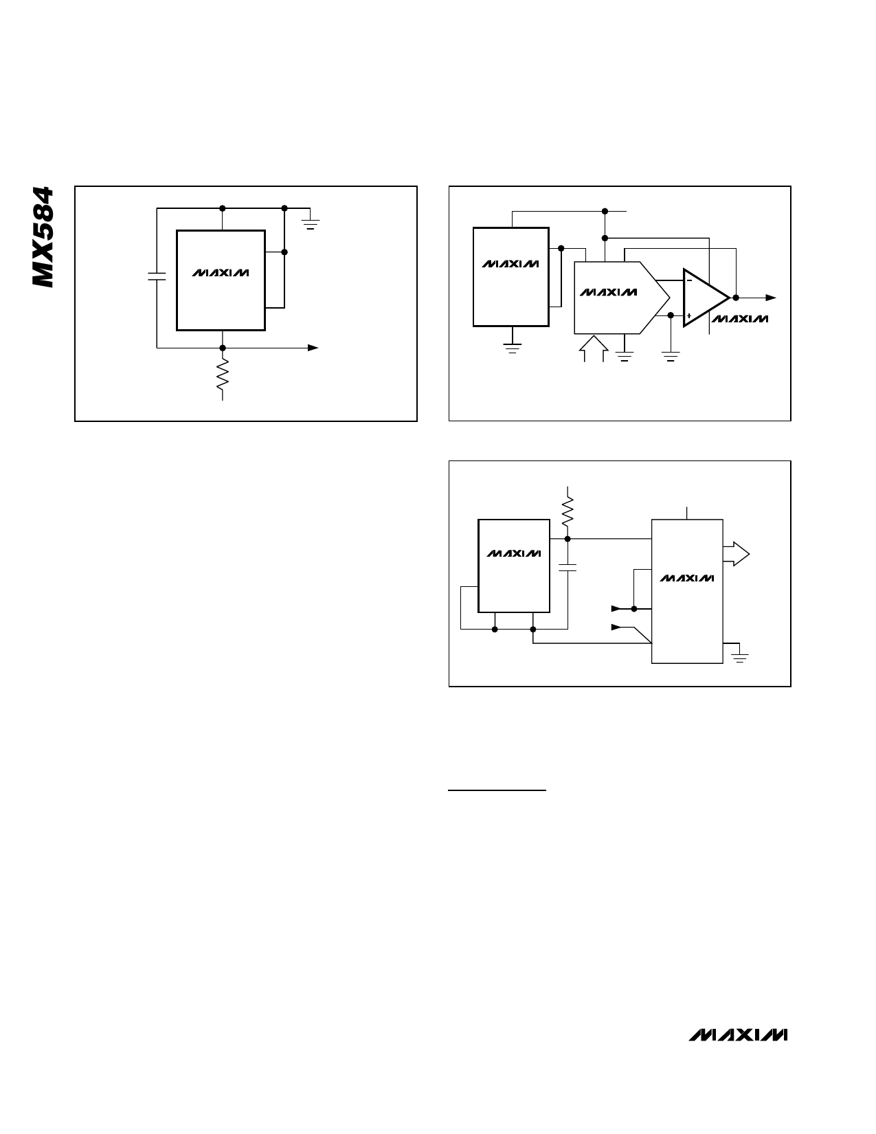
+VS
1
10V
0.01µF
MX584
COM
4
5V 2
5V
RS
2.4kΩ
5%
-15V
Figure 9. Two-Terminal -5V Reference
ANALOG
GROUND
VREF = -5V
Output Current
The MX584 is capable of sinking as well as sourcing
current. The circuit is also protected for output shorts to
either +VS or ground (COMMON). The output’s voltage
versus current characteristic is shown in the Typical
Operating Characteristics section. For applications that
require the MX584 to sink current, maintain a load
capacitance of 10nF or greater for proper operation.
Dynamic Performance
The turn-on settling performance of the MX584 is
shown in the Typical Operating Characteristics. Both
coarse and fine transient response is shown. The refer-
ence typically settles to 1mV (10V output) within 180µs
after power is applied.
Noise Filtering
The bandwidth of the MX584’s output amplifier can be
limited by connecting a capacitor between the CAP
and VBG pins (see Figure 4). Typical values range from
0.01µF to 0.1µF. The reduction of wideband and
feedthrough noise is plotted in a graph in the Typical
Operating Characteristics section.
Strobe Input
The STROBE input, pin 5, zeroes the reference output
when it is pulled LOW. If no current is pulled from
STROBE, operation is normal. The threshold of the
input is 200mV, so an open-drain n-channel FET or
open-collector transistor driven from logic is recom-
mended (see Figure 5). The current-sinking ability
should be at least 500µA and the leakage current
should be 5µA or less. While shut down, the MX584
should not be required to source or sink current unless
a 0.7V residual output is acceptable. If the reference is
required to sink transient current while shut down, the
8
+VS
1
10V
MX584
2
5V
COM
4
7.5V to 15V
5V
15
14 16
RFB
1
OUT1
MX7533
VREF
OUT2
GND
2
3
4-13
DIGITAL
INPUT
VOUT
0 TO -5V
MAX400
-7.5V
TO -15V
Figure 10. Low-Power, 10-Bit CMOS DAC Connection
-5V
COM 4
MX584
8 +VS
10V 2.5V
1
3
1kΩ
5%
-2.5VREF
0.01µF
INPUT
0 TO +2.5V
2 VREF
BOFS
+5V
1
VDD
DB0–
DB7
13-6
DIGITAL
OUTPUTS
MX7574
AIN
5 AGND
DGND 18
Figure 11. MX584 as Negative 2.5V Reference for a CMOS
ADC
current flowing out of STROBE should be limited with
100Ω as shown in the dashed connection in Figure 5.
Applications Information
Precision High-Current Reference
A PNP power transistor, or Darlington, is easily connect-
ed to the MX584 to greatly increase its output current.
The circuit in Figure 6 provides a +10V output at up to
4A. If the load has a significant capacitive component,
C1 should be added. If the load is purely resistive, high-
frequency supply rejection is improved without C1. An
NPN output transistor or Darlington can also be used to
boost output current as shown in Figure 7.
Current Limiter
By adding a single resistor as shown in Figure 8, the
MX584 is turned into a precision current limiter for
6 _______________________________________________________________________________________
Share Link: 