MT9079 Просмотр технического описания (PDF) - Mitel Networks
Номер в каталоге
Компоненты Описание
производитель
MT9079 Datasheet PDF : 54 Pages
| |||
MT9079
G.704 and G.732 for more details on CAS
mutliframing requirements.
A CAS signalling multiframe consists of 16 basic
frames (numbered 0 to 15), which results in a
multiframe repetition rate of 2 msec. It should be
noted that the boundaries of the signalling
multiframe may be completely distinct from those of
the CRC-4 multiframe. CAS multiframe alignment is
based on a multiframe alignment signal (a 0000 bit
sequence), which occurs in the most significant
nibble of time slot 16 of basic frame zero of the CAS
multiframe. Bit 6 of this time slot is the multiframe
alarm bit (usually designated Y). When CAS
multiframing is acquired on the receive side, the
transmit Y-bit is zero; when CAS multiframing is not
acquired, the transmit Y-bit is one. Bits 5, 7 and 8
(usually designated X) are spare bits and are
normally set to one if not used.
Time slot 16 of the remaining 15 basic frames of the
CAS multiframe (i.e., basic frames 1 to 15) are
reserved for the ABCD signalling bits for the 30
payload channels. The most significant nibbles are
the reserved for channels 1 to 15 and the least
significant nibbles are reserved for channels 16 to
30. That is, time slot 16 of basic frame 1 has ABCD
for channel 1 and 16, time slot 16 of basic frame 2
has ABCD for channel 2 and 17, through to time slot
16 of basic frame 15 has ABCD for channel 15 and
30.
MT9079 Access and Control
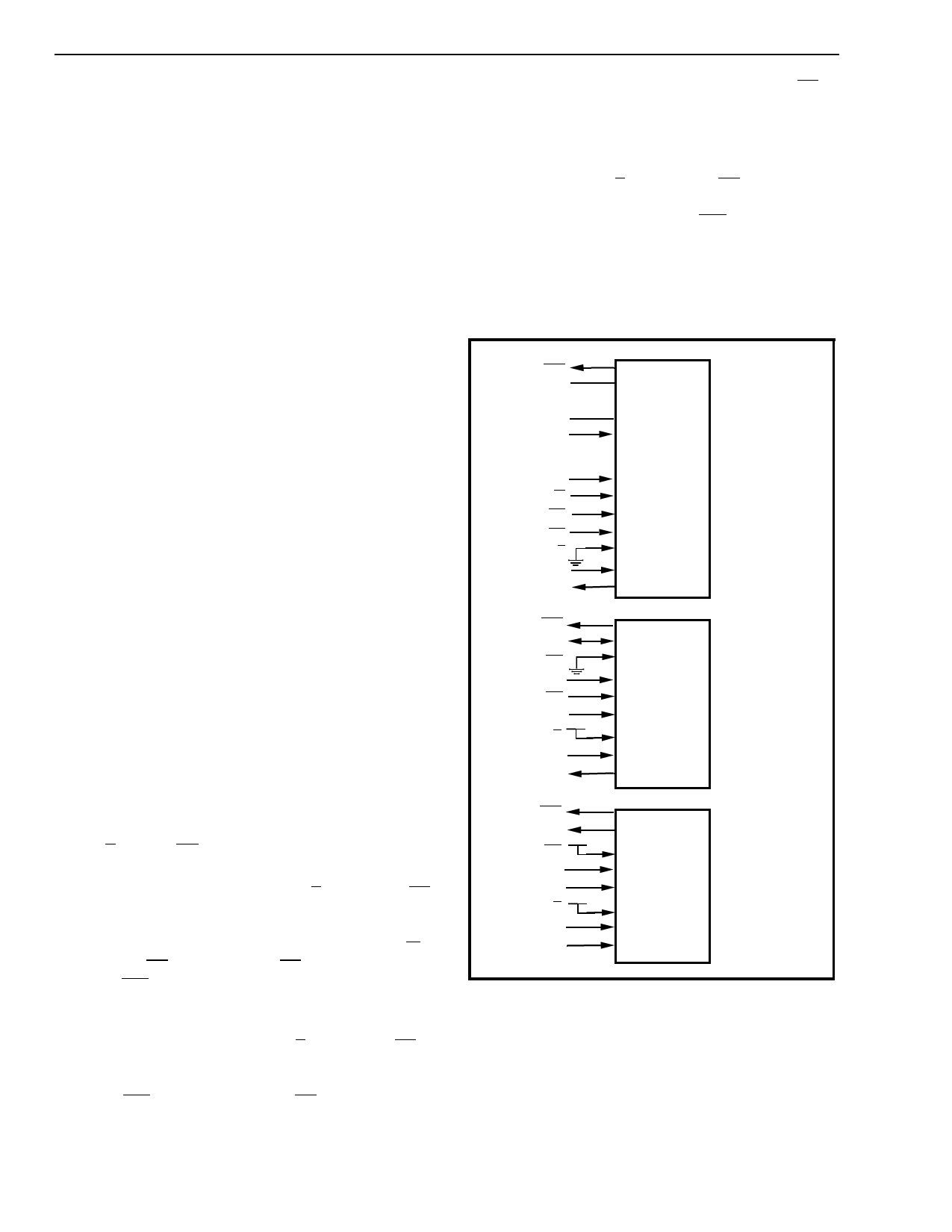
The Control Port Interface
The control and status of the MT9079 is achieved
through one of three generic interfaces, which are
parallel microprocessor, serial microcontroller, and
ST-BUS. This control port selection is done through
pins S/P and ST/SC.
The parallel microprocessor port (S/P = 0 and ST/SC
= AC4) is non-multiplexed and consists of an eight
bit bidirectional data bus (D0-D7), a five bit
address/command bus (AC0-AC4), read/write (R/W),
chip select (CS), data strobe (DS) and an interrupt
request (IRQ). This port can be easily interfaced to
most high speed parallel microprocessors.
The serial microcontroller port (S/P = 1 and ST/SC =
0) consists of a receive data input (RxD), serial clock
input (SCLK), serial data input/output (SIO), interrupt
request (IRQ), and chip select (CS). This port will
automatically interface to Intel, Motorola or National
microcontrollers in either synchronous or
asynchronous modes. When controller mode is
selected, the SCLK input is sampled when CS is
brought low. If SCLK is high the device is in Intel
mode; if SCLK is low it will be in Motorola/National
Microwire mode.
The ST-BUS port (S/P = 1 and ST/SC = 1) consists
of control streams CSTi0 and CSTi1, status stream
CSTo0, and interrupt request (IRQ). It should be
noted that in this mode access to the circular buffers
and notional bit buffers is not provided. This port
meets the requirements of the "ST-BUS Generic
Device Specification", Mitel Application Note
MSAN-126.
IRQ
D0
•••
D7
AC4
•••
AC0
R/W
CS
DS
S/P
CSTi2
CSTo1
IRQ
RxD
ST/SC
SIO
CS
SCLK+5V
S/P
CSTi2
CSTo1
PARALLEL µP
CONTROL
INTERFACE
SERIAL µP
CONTROL
INTERFACE
IRQ
CSTo0
+5V
ST/SC
CSTi0
CSTi1
+5V
S/P
CSTi2
CSTo1
ST-BUS
CONTROL
INTERFACE
Figure 3 - Control Port Interface
Control and Status Register Access
The parallel microprocessor and serial
microcontroller interfaces gain access to specific
registers of the MT9079 through a two step process.
First, writing to the Command/Address Register
(CAR) selects one of the 14 pages of control and
status registers (CAR address: AC4 = 0, AC3-AC0 =
4-244
Share Link: 