MOC8101(2008) Просмотр технического описания (PDF) - Vishay Semiconductors
Номер в каталоге
Компоненты Описание
производитель
MOC8101 Datasheet PDF : 7 Pages
| |||
MOC8101/MOC8102/MOC8103/MOC8104/MOC8105
Optocoupler, Phototransistor Output, Vishay Semiconductors
No Base Connection
ELECTRICAL CHARACTERISTICS
PARAMETER
TEST CONDITION
PART SYMBOL MIN.
TYP.
MAX.
UNIT
COUPLER
Saturation voltage collector emitter
IF = 5.0 mA
VCEsat
0.25
0.4
V
Coupling capacitance
CC
0.6
pF
Note
Tamb = 25 °C, unless otherwise specified.
Minimum and maximum values are testing requirements. Typical values are characteristics of the device and are the result of engineering
evaluation. Typical values are for information only and are not part of the testing requirements.
CURRENT TRANSFER RATIO
PARAMETER
TEST CONDITION
Current transfer ratio
VCE = 10 V, IF = 10 mA
PART
MOC8101
MOC8102
MOC8103
MOC8104
MOC8105
SYMBOL
CTR
CTR
CTR
CTR
CTR
MIN.
50
73
108
160
65
TYP.
MAX.
80
117
173
256
133
UNIT
%
%
%
%
%
SWITCHING CHARACTERISTICS
PARAMETER
Turn-on time
Turn-off time
Rise time
Fall time
Cut off frequency
TEST CONDITION
VCC = 10 V, IC = 2.0 mA, RL = 100 Ω
VCC = 10 V, IC = 2.0 mA, RL = 100 Ω
VCC = 10 V, IC = 2.0 mA, RL = 100 Ω
VCC = 10 V, IC = 2.0 mA, RL = 100 Ω
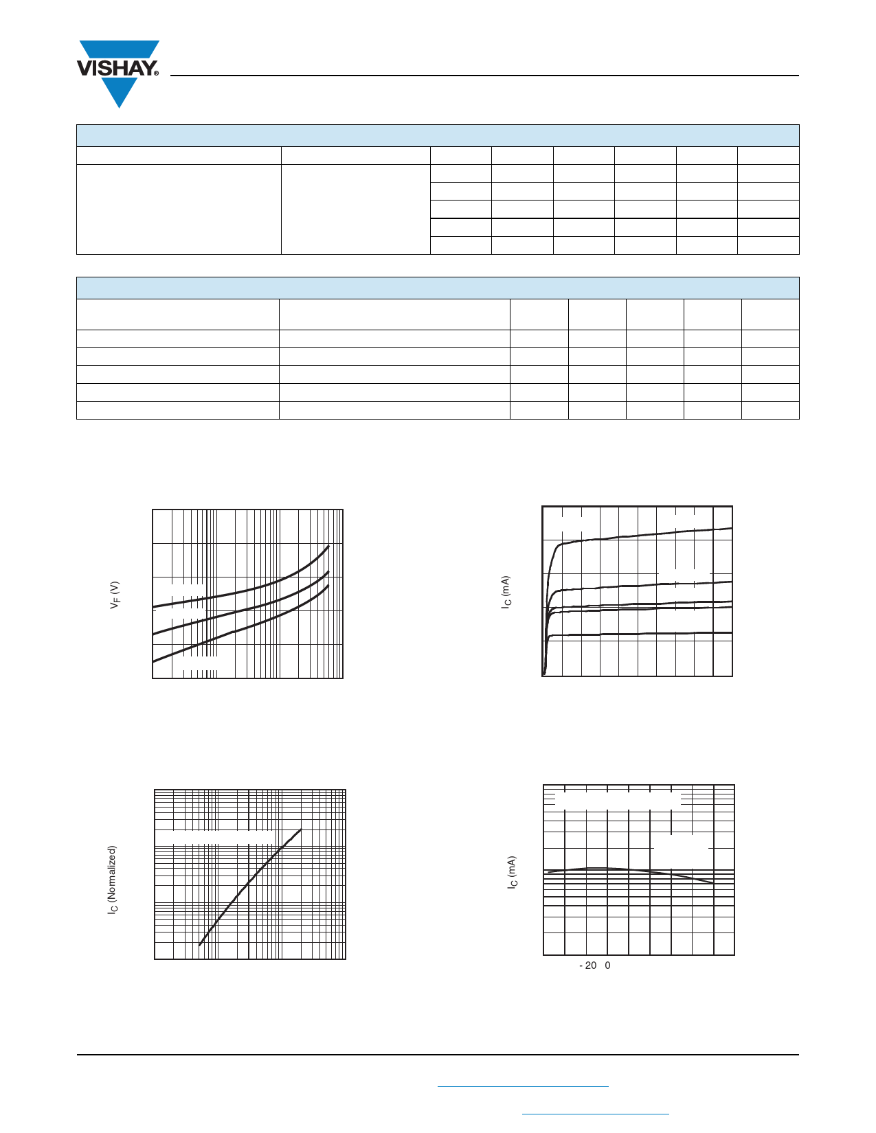
TYPICAL CHARACTERISTICS
Tamb = 25 °C unless otherwise specified
SYMBOL
ton
toff
tr
tf
fco
MIN.
TYP.
3.0
2.3
2.0
2.0
250
MAX.
UNIT
µs
µs
µs
µs
kHz
1.7
1.5
1.3
TA = 55 °C
1.1
TA = 25 °C
0.9
TA = 100 °C
0.7
0.1
1
10
imoc8101_02
IF (mA)
100
Fig. 1 - Forward Voltage vs. Forward Current
10
1
Normalized to IF = 10 mA
0.1
0.01
0.1
1
10
100
imoc8101_03
I F(mA)
Fig. 2 - Collector Current vs. LED Forward Current
Document Number: 83660
Rev. 1.5, 11-Jan-08
For technical questions, contact: optocoupler.answers@vishay.com
www.vishay.com
3
Share Link: 