MMA7456L –Я—А–Њ—Б–Љ–Њ—В—А —В–µ—Е–љ–Є—З–µ—Б–Ї–Њ–≥–Њ –Њ–њ–Є—Б–∞–љ–Є—П (PDF) - Freescale Semiconductor
–Э–Њ–Љ–µ—А –≤ –Ї–∞—В–∞–ї–Њ–≥–µ
–Ъ–Њ–Љ–њ–Њ–љ–µ–љ—В—Л –Ю–њ–Є—Б–∞–љ–Є–µ
–њ—А–Њ–Є–Ј–≤–Њ–і–Є—В–µ–ї—М
MMA7456L Datasheet PDF : 36 Pages
| |||
LEVEL DETECTION
When in Level or Pulse detection mode, it is not advisable to read the XYZ measurements because this can conflict with timing.
The interrupts for level and pulse detection are at 600 Hz, while measurement mode is at 125 Hz. It is best to exit the pulse/level
mode before taking a measurement on the XYZ.
Both the Level Detection and Pulse Detection modes can trigger an interrupt. Typically one interrupt is assigned to either pulse
detection or level detection. To detect both at the same time 2 interrupts are required. The level detection mechanism has no
timers associated with it. Once a set acceleration level is reached the interrupt pin will go high and remain high until the interrupt
pin is cleared (See Assigning, Clearing & Detecting Interrupts).
By default all three axes are enabled and the detection range is 8g only. X and/or Y and/or Z can be disabled. There is a choice
between detecting an Absolute signal or a Positive or Negative only signal on the enabled axes. There is also a choice between
doing a detection for Motion where X or Y or Z > Threshold vs. doing a detection for Freefall where X& Y & Z < Threshold.
$18: Control 1 (Read/Write) Setting the Detection Axes for X, Y and Z
This allows the user to define how many axes to use for detection. All axes are enabled by default. To disable write 1.
XDA: Disable X
YDA: Disable Y
ZDA: Disable Z
D7
DFBW
0
D6
THOPT
0
D5
ZDA
0
D4
YDA
0
D3
XDA
0
D2
INTREG[1]
0
D1
INTREG[0]
0
D0
INTPIN
0
Reg $18
Function
Default
$19: Control 2 (Read/Write) Motion Detection (OR Condition) or Freefall Detection (AND Condition)
LDPL = 0: Level detection polarity is positive and detecting condition is OR for all 3 axes.
X or Y or Z > Threshold
||X|| or ||Y|| or ||Z|| > Threshold
LDPL = 1: Level detection polarity is negative detecting condition is AND for all 3 axes.
X and Y and Z < Threshold
||X|| and ||Y|| and ||Z|| < Threshold
D7
D6
D5
D4
D3
D2
D1
D0
--
--
--
--
--
DRVO
PDPL
LDPL
0
0
0
0
0
0
0
0
Reg $19
Function
Default
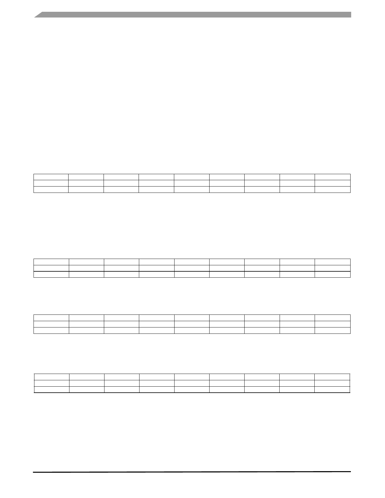
$18: Control 1 (Read/Write): Setting the threshold to be an integer value or an absolute value
This allows the user to set the threshold to be absolute, or to be based on the threshold value as positive or negative.
THOPT = 0 Absolute; THOPT = 1 Positive Negative
D7
DFBW
0
D6
THOPT
0
D5
ZDA
0
D4
YDA
0
D3
XDA
0
D2
INTREG[1]
0
D1
INTREG[0]
0
D0
INTPIN
0
Reg $18
Function
Default
$1A: Level Detection Threshold Limit Value (Read/Write)
When an event is detected the interrupt pin (either INT1 or INT2) will go high. The interrupt pin assignment is set up in Register
$18, discussed in the Assigning, Clearing & Detecting Interrupts section. The detection status is monitored by the Detection
Source Register $0A.
D7
LDTH[7]
0
D6
LDTH[6]
0
D5
LDTH[5]
0
D4
LDTH[4]
0
D3
LDTH[3]
0
D2
LDTH[2]
0
D1
LDTH[1]
0
D0
LDTH[0]
0
Reg $1A
Function
Default
LDTH[7:0]: Level detection threshold value. If THOPT bit in Detection Control Register is вАЬ0вАЭ, it is unsigned 7 bits value and
LDTH[7] should be вАЬ0вАЭ. If THOPT bit is вАЬ1вАЭ, it is signed 8 bits value.
MMA7456L
10
Sensors
Freescale Semiconductor
Share Link: 