EVAL-AD7818EB Просмотр технического описания (PDF) - Analog Devices
Номер в каталоге
Компоненты Описание
производитель
EVAL-AD7818EB
Analog Devices

EVAL-AD7818EB Datasheet PDF : 20 Pages
| |||
AD7816/AD7817/AD7818
ABSOLUTE MAXIMUM RATINGS1
(TA = 25°C unless otherwise noted)
VDD to AGND . . . . . . . . . . . . . . . . . . . . . . . . . –0.3 V to +7 V
VDD to DGND . . . . . . . . . . . . . . . . . . . . . . . . . –0.3 V to +7 V
Analog Input Voltage to AGND
VIN1 to VIN4 . . . . . . . . . . . . . . . . . . . –0.3 V to VDD + 0.3 V
Reference Input Voltage to AGND2 . . . –0.3 V to VDD + 0.3 V
Digital Input Voltage to DGND . . . . . . –0.3 V to VDD + 0.3 V
Digital Output Voltage to DGND . . . . . –0.3 V to VDD + 0.3 V
Storage Temperature Range . . . . . . . . . . . . . –65°C to +150°C
Junction Temperature . . . . . . . . . . . . . . . . . . . . . . . . . . 150°C
TSSOP, Power Dissipation . . . . . . . . . . . . . . . . . . . . 450 mW
θJA Thermal Impedance . . . . . . . . . . . . . . . . . . . . . 120°C/W
Lead Temperature, Soldering . . . . . . . . . . . . . . . . . . 260°C
Vapor Phase (60 sec) . . . . . . . . . . . . . . . . . . . . . . . 215°C
Infrared (15 sec) . . . . . . . . . . . . . . . . . . . . . . . . . . 220°C
16-Lead SOIC Package, Power Dissipation . . . . . . . . 450 mW
θJA Thermal Impedance . . . . . . . . . . . . . . . . . . . . . 100°C/W
Lead Temperature, Soldering
Vapor Phase (60 sec) . . . . . . . . . . . . . . . . . . . . . . . 215°C
Infrared (15 sec) . . . . . . . . . . . . . . . . . . . . . . . . . . 220°C
8-Lead SOIC Package, Power Dissipation . . . . . . . . . . 450 mW
θJA Thermal Impedance . . . . . . . . . . . . . . . . . . . . . 157°C/W
Lead Temperature, Soldering
Vapor Phase (60 sec) . . . . . . . . . . . . . . . . . . . . . . . 215°C
Infrared (15 sec) . . . . . . . . . . . . . . . . . . . . . . . . . . 220°C
µSOIC Package, Power Dissipation . . . . . . . . . . . . . . 450 mW
θJA Thermal Impedance . . . . . . . . . . . . . . . . . . . . . 206°C/W
Lead Temperature, Soldering
Vapor Phase (60 sec) . . . . . . . . . . . . . . . . . . . . . . . 215°C
Infrared (15 sec) . . . . . . . . . . . . . . . . . . . . . . . . . . 220°C
NOTES
1Stresses above those listed under Absolute Maximum Ratings may cause perma-
nent damage to the device. This is a stress rating only; functional operation of the
device at these or any other conditions above those listed in the operational sections
of this specification is not implied. Exposure to absolute maximum rating condi-
tions for extended periods may affect device reliability.
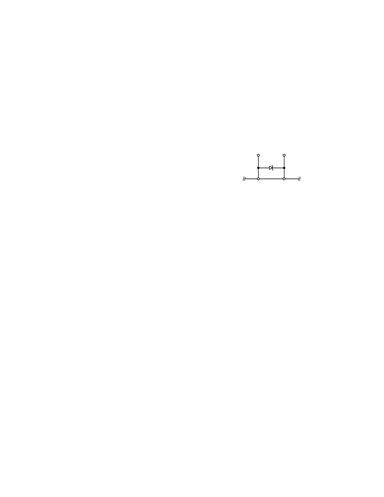
2If the Reference Input Voltage is likely to exceed VDD by more than 0.3 V (e.g.,
during power-up) and the reference is capable of supplying 30 mA or more, it is
recommended to use a clamping diode between the REFIN pin and VDD pin. The
diagram below shows how the diode should be connected.
REFIN
VDD
BAT81
AD7816/AD7817
–6–
REV. C
Share Link: