MIC3838(2003) Просмотр технического описания (PDF) - Micrel
Номер в каталоге
Компоненты Описание
производитель
MIC3838 Datasheet PDF : 11 Pages
| |||
MIC3838/3839
Ordering Information
Part Number
MIC3838BMM
MIC3839BMM
Turn On
Threshold
12.5V
4.3V
Turn Off
Threshold
8.3V
4.1V
Temperature Range
–40°C to +85°C
–40°C to +85°C
Package
MSOP-10
MSOP-10
Micrel
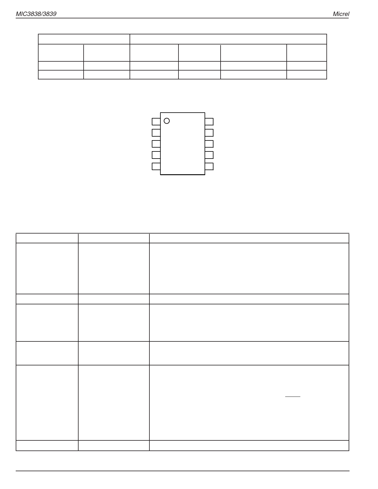
Pin Configuration
COMP 1
FB 2
ILIM 3
RAMP 4
RC 5
10 VREF
9 VDD
8 OUTA
7 OUTB
6 GND
MSOP-10 (MM)
Pin Description
Pin Number
1
2
3
4
5
6
Pin Name
COMP
FB
ILIM
RAMP
RC
GND
Pin Function
COMP is the output of the error amplifier and the input of the PWM
comparator. The error amplifier in the MIC3838 is a true low-output imped-
ance, 4MHz operational amplifier. As such, the COMP pin can both source
and sink current. However, the error amplifier is internally current limited, so
that zero duty cycle can be externally forced by pulling COMP to GND.
The MIC3838 family features built-in full cycle soft start. Soft start is imple-
mented as a clamp on the maximum COMP voltage.
The inverting input to the error amplifier.
The input to the peak current, and overcurrent comparators. The
overcurrent comparator is only intended for fault sensing. Exceeding the
overcurrent threshold will cause a soft start cycle. An internal MOSFET
discharges the current sense filter capacitor to improve dynamic perfor-
mance of the power converter.
Input to the PWM comparator. Sawtooth ramp for PWM control. Allows for
either current-mode or voltage-mode control. An internal MOSFET dis-
charges the current sense filter capacitor.
The oscillator programming pin. Only two components are required to
program the oscillator, a resistor (tied between VDD and RC), and a capaci-
tor (tied between RC and GND). The approximate oscillator frequency is
determined by the simple formula:
FOSCILLATOR
=
1.41
R×C
The recommended range of timing resistors is between 7kΩ and 200kΩ and
range of timing capacitors is between 100pF and 1000pF. Timing resistors
less than 7kΩ should be avoided. For best performance, keep the leads
between components as short as possible. Separate ground and VDD
traces to the external timing network are encouraged.
Ground. Return path for signal and gate drive functions.
MIC3838/3839
2
August 2003
Share Link: 