MC33794 Просмотр технического описания (PDF) - Motorola => Freescale
Номер в каталоге
Компоненты Описание
производитель
MC33794 Datasheet PDF : 20 Pages
| |||
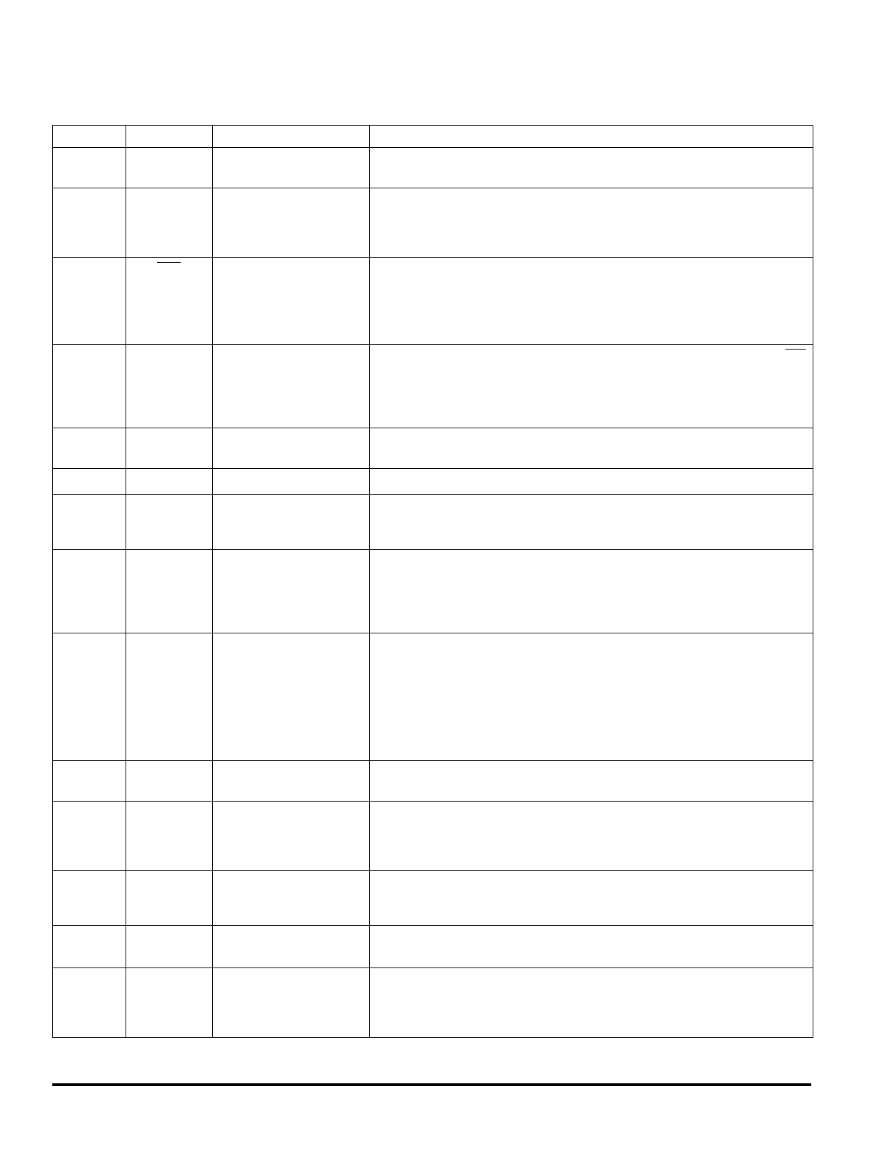
HSOP PIN FUNCTION DESCRIPTION (continued)
Pin
Pin Name
Formal Name
21
ISO-9141
ISO-9141 Bus
22
LAMP_OUT
Lamp Driver
23
RST
Reset
24
WD_IN
Watchdog Input
25
LAMP_GND
26
LAMP_CTRL
28
LAMP_SENSE
Lamp Ground
Lamp Control
Lamp Sense
29
LAMP_MON
Lamp Monitor
30
DIS_SHIELD
Shield Driver Disable
34–31
35
A, B, C, D
SIGNAL
Selector Inputs
Undetected Signal
36
LEVEL
Detected Level
37
PWR_MON
Power Monitor
38
LP_CAP
Low-Pass Filter Capacitor
Definition
This pin connects to the ISO-9141 bus. It provides the drive and detects signaling on
the bus and translates it from the bus level to logic levels for the MCU.
This is an active low output capable of sinking current of a typical indicator lamp. One
end of the lamp should be connected to a positive supply (for example, battery
voltage) and the other side to this pin. The current is limited to prevent damage to the
IC in the case of a short or surge during lamp turn-on or burn-out.
This output is intended to generate the reset function of a typical MCU. It has a delay
for power-on reset, level detectors to force a reset when VCC is out-of-range high or
low, and a watchdog timer that will force a reset if WD_IN is not asserted at regular
intervals. Timing is derived from the oscillator and will change with changes in the
resistor attached to R_OSC.
This pin must be asserted and deasserted at regular interval in order to prevent RST
from being asserted. By having the MCU program perform this operation more often
the allowed time, a check that the MCU is running and executing its program is
assured. If this doesn’t occur, the MCU will be reset. If the watchdog function is not
desired, this pin may be connected to CLK to prevent a reset from being issued.
This is the ground for the current from the lamp. The current into LAMP_OUT flows
out through this pin.
This signal is used to control the lamp driver. A high logic level turns on the lamp.
This pin is normally connected to the LAMP_OUT pin. The voltage at this pin is
reduced and sent to LAMP_MON so the voltage at the lamp pin is brought into the
range of the analog-to-digital converter (ADC) in the MCU.
This pin is connected through a voltage divider to the LAMP_SENSE pin. The voltage
divider scales the voltage at this pin so that battery voltage present when the lamp is
off is scaled to the range of the MCU ADC. With the lamp off, this pin will be very close
to battery voltage if the lamp is not burned out and the pin is not shorted to ground.
This is useful as a lamp check.
This pin is used to turn off the shield signal. The purpose of doing this is to be able to
detect that the shield signal is not working or the connection to the coax shields is
broken. If either of these conditions exists, there will be little or no change in the
capacitance measured when the DIS_SHIELD is asserted. If the SHIELD output is
working and properly connected, the capacitance of the coax will not be cancelled
when this pin is asserted and the measured capacitance will appear to change by
approximately the capacitance between the center conductor and the shield in the
coax.
These input pins control which electrode or reference is active. Selection values are
shown in Table 1, Electrode Selection, page 14.
This is the undetected signal being applied to the detector. It has a DC level with the
low radio frequency signal superimposed on it. Care must be taken to minimize DC
loading of this signal. A shift of DC will change the center point of the signal and
adversely affect the detection of the signal.
This is the detected, amplified, and offset representation of the signal voltage on the
selected electrode. Filtering of the rectified signal is performed by a capacitor
attached to LP_CAP.
This is connected through a voltage divider to VPWR. It allows reduction of the voltage
so it will fall within the range of the ADC on the MCU.
A capacitor on this pin forms a low pass filter with the internal series resistance from
the detector to this pin. This pin can be used to determine the detected level before
amplification or offset is applied. A 10 nF capacitor connected to this pin will smooth
the rectified signal. More capacitance will increase the response time unnecessarily.
33794
4
MOTOROLA ANALOG INTEGRATED CIRCUIT DEVICE DATA
Share Link: 