MC33794 Просмотр технического описания (PDF) - Motorola => Freescale
Номер в каталоге
Компоненты Описание
производитель
MC33794 Datasheet PDF : 20 Pages
| |||
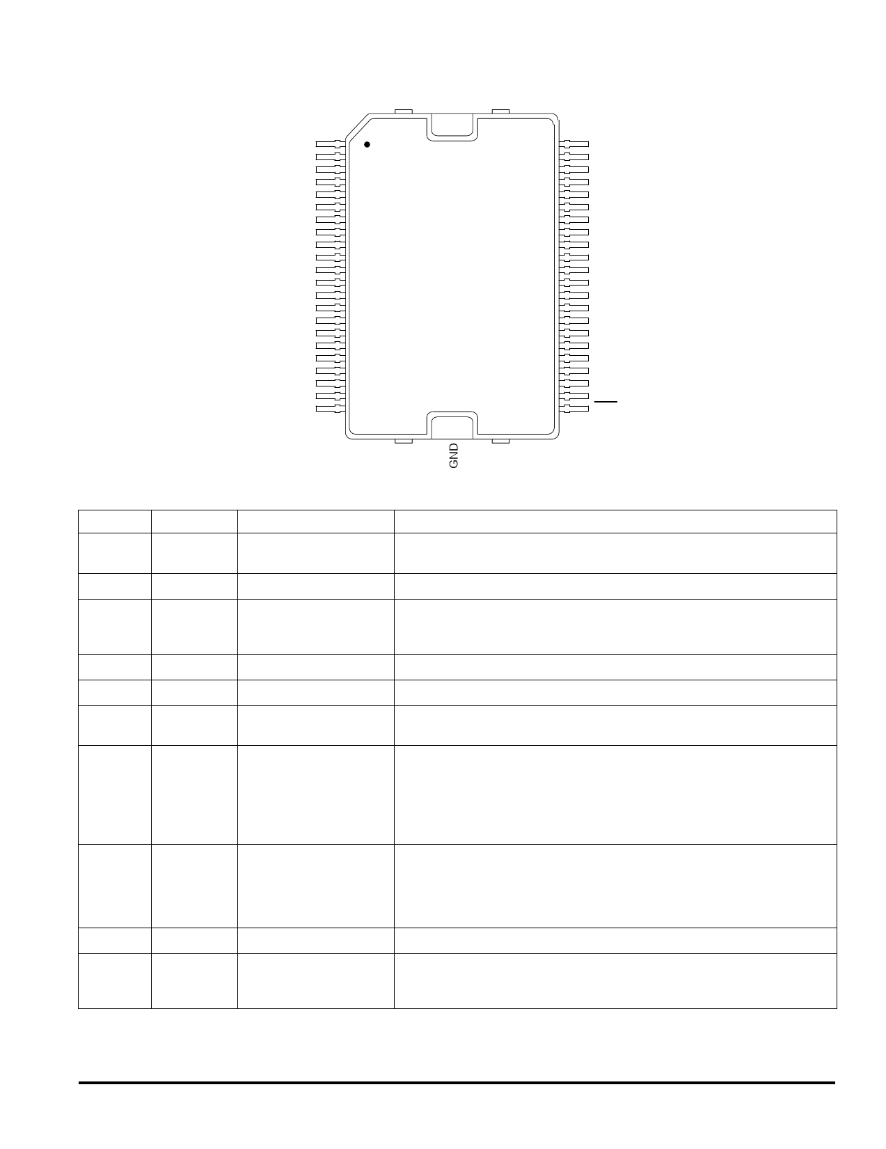
VCC
1
NC
2
AGND
3
SHIELD
4
NC
5
GND
6
TEST
7
E1
8
E2
9
E3
10
E4
11
E5
12
E6
13
E7
14
E8
15
E9
16
REF_A
17
REF_B
18
ISO_OUT
19
ISO_IN
20
ISO-9141
21
LAMP_OUT
22
HEAT
SINK
44
VPWR
43
NC
42
VDD
41
VDD_MON
40
CLK
39
R_OSC
38
LP_CAP
37
PWR_MON
36
LEVEL
35
SIGNAL
34
A
33
B
32
C
31
D
30
DIS_SHIELD
29
LAMP_MON
28
LAMP_SENSE
27
NC
26
LAMP_CTRL
25
LAMP_GND
24
WD_IN
23
RST
HSOP PIN FUNCTION DESCRIPTION
Pin
Pin Name
Formal Name
1
VCC
5.0 V Regulator Output
2, 5, 27, 43
3
NC
AGND
No connect
Analog Ground
4
6, Heat Sink
7
SHIELD
GND
TEST
8 – 16
E1 – E9
Shield Driver
Ground
Test Mode Control
Electrode Connections
17, 18
REF_A,
REF_B
Reference Connections
19
ISO_OUT
20
ISO_IN
ISO-9141 Output
ISO-9141 Input
Definition
This output pin requires a 47 µF capacitor and provides a regulated 5.0 V for the
MCU and for internal needs of the 33794.
These pins may be used at some future date and should be left open.
This pin is connected to the ground return of the analog circuitry. This ground should
be kept free of transient electrical noise like that from logic switching. Its path to the
electrical current return point should be kept separate from the return for GND.
This pin connects to cable shields to cancel cable capacitance.
This pin and metal backing is the IC power return and thermal radiator/conductor.
This pin is normally connected to circuit ground. There are special operating modes
associated with this pin when it is not at ground.
These are the electrode pins. They are connected either directly or through coaxial
cables to the electrodes for measurements. One of these electrodes can be selected
at a time for capacitance measurement. All of the other unselected electrodes are
grounded by an internal switch. The signal at the selected electrode pin is routed to
the shield driver amplifier by an internal switch. All of the coaxial cable shields should
be isolated from ground and connected SHIELD.
These pins can be individually selected like E1 through E9. Unlike E1 through E9,
these pins are not grounded when not selected. The purpose of these pins is to allow
known capacitors to be measured. By using capacitors at the low and high end of the
expected range, absolute values for the capacitance on the electrodes can be
computed.
This pin translates ISO-9141 receive levels to 5.0 V logic levels for the MCU.
This pin accepts data from the MCU to be sent over the ISO-9141 communications
interface. It translates the 5.0 V logic levels from the MCU to transmit levels on the
ISO-9141 bus.
MOTOROLA ANALOG INTEGRATED CIRCUIT DEVICE DATA
33794
3
Share Link: 