MC13146FTA Просмотр технического описания (PDF) - Motorola => Freescale
Номер в каталоге
Компоненты Описание
производитель
MC13146FTA Datasheet PDF : 16 Pages
| |||
Freescale SMeCm1i3c14o6nductor, Inc.
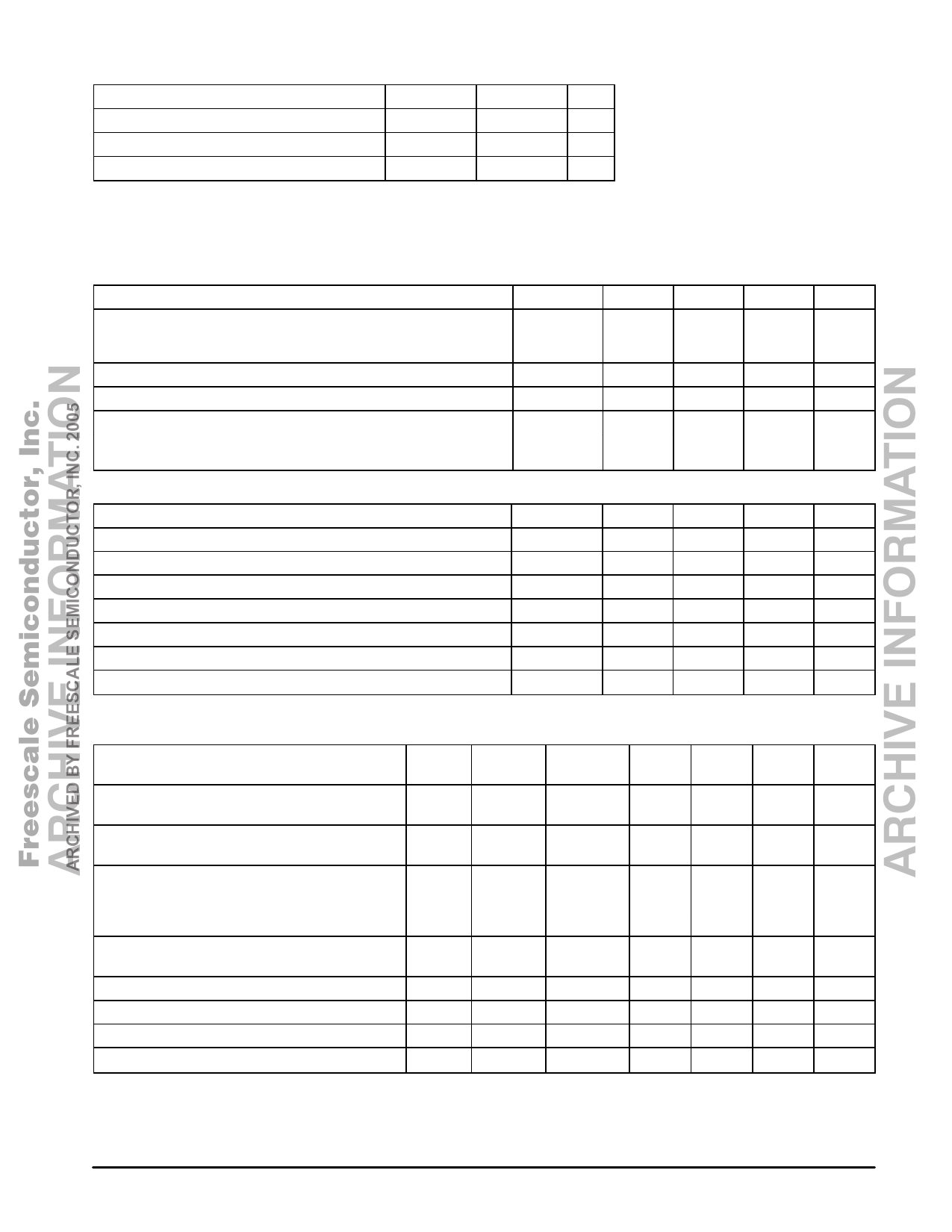
MAXIMUM RATINGS
Rating
Symbol
Value
Unit
ÁÁÁÁÁÁÁÁÁÁÁÁÁÁÁÁÁÁÁÁÁÁÁ ARPoCwHerIVSuEppDlyBVoYltaFgeREESCALE SEMICONDVCUCC(mTaOx)R, INC.7.20005 Vdc
ÁÁÁÁÁÁÁÁÁÁÁÁÁÁÁÁÁÁÁÁÁÁÁ Junction Temperature
TJ(max)
150
°C
ÁÁÁÁÁÁÁÁÁÁÁÁÁÁÁÁÁÁÁÁÁÁÁÁÁÁÁÁÁÁÁÁÁÁÁÁÁÁÁÁÁÁÁÁÁÁ Storage Temperature Range
Tstg
–65 to 150
°C
NOTES: 1. Maximum Ratings are those values beyond which damage to the device may occur.
Functional operation should be restricted to the limits in the Recommended Operating
Conditions, Electrical Characteristics tables or Pin Descriptions section.
2. Meets Human Body Model (HBM) ≤100 V and Machine Model (MM) ≤25 V. ESD data
available upon request.
RECOMMENDED OPERATING CONDITIONS
Characteristic
Power Supply Voltage (TA = 25°C)
RF Frequency Range
Ambient Temperature Range
Maximum Input Signal Level
– with no damage
– with minor performace degradation
Symbol
Min
Typ
Max
Unit
VCC
VEE
fRF
TA
PIF
2.7
–
6.5
Vdc
–
0
–
Vdc
1.0
–
2500
MHz
–20
–
70
°C
–
–10
–
dBm
–
15
–
dBm
TRANSMITTER DC ELECTRICAL CHARACTERISTICS (TA = 25°C, VCC = 3.6 Vdc, no input signal, unless otherwise noted)
Characteristic
Symbol
Min
Typ
Max
Unit
Total Supply Current (Enable = VCC)
Power Down Current (Enable = VEE)
MC Current Input (High)
MC Current Input (Low)
Input high voltage
Input low voltge
Input Current
Itotal
15
18
21
mA
Itotal
-
30
100
µA
Iih
70
100
130
µA
Iil
–130
–100
–70
µA
Vih
VCC – 0.4
–
–
V
Vil
–
–
0.4
V
Iin
–50
–
50
µA
TRANSMITTER AC ELECTRICAL CHARACTERISTICS (TA = 25°C, VCC = 3.6 Vdc, Enable = 3.6 Vdc, per Test Circuit shown in
Figure 1, unless otherwise noted)
Characteristics
Input Measure
Pin
Pin
Symbol
Min
Typ
Max
Unit
Amplifier Output Power (with external matching)
@ 950 MHz; Pin = –19 dBm
PAin
PAout
PA_PO
–4.5
–3.3
–2.1
dBm
Amplifier 1.0 dB Compression Point (@ 950 MHz =
PAin
PAout
P1dBC.Pt.
–
8.0
–
dBm
fIF_out)
Amplifier Output Harmonics (with external matching)
PAin
PAout
dBc
@ 950 MHz; Pin = –19 dBm
2nd
PA – 2f
–25
–37
–
3rd
PA – 3f
–35
–52
–
Mixer/Buffer Output (@ 950 MHz = fosc; Mixer input
(Pin 5) pulled through 270 Ω resistor)
Buf_out+ PMx/Buf_out –19
–18
–17
dBm
PLL Setup Time [Note 1]
Mixer Input Third Order Intercept Point
MC
PRSCout
TPLL
IIP3
-
10
–
nS
–
10
–
dBm
VCO Phase Noise (@ 10 kHz offset)
Buf_out+
–
–80
–
dBc/Hz
Prescalar Output Level (10 k || 8.0 pF Load)
PRSCout
400
–
600
mVpp
NOTES: 1. MC input (50%) to PRSCout rising output (50%) for proper modulus selection.
2. Typical performance parameters indicate the potential of the device under ideal operation conditions.
2
For More Information On This Product, MOTOROLA RF/IF DEVICE DATA
Go to: www.freescale.com
Share Link: 