MC100LVEP111FAG Просмотр технического описания (PDF) - ON Semiconductor
Номер в каталоге
Компоненты Описание
производитель
MC100LVEP111FAG Datasheet PDF : 10 Pages
| |||
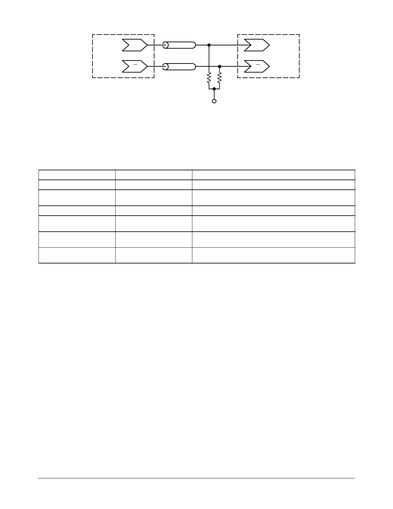
MC100LVEP111
Q
Driver
Device
Q
Zo = 50 W
Zo = 50 W
50 W
50 W
D
Receiver
Device
D
VTT
VTT = VCC − 2.0 V
Figure 5. Typical Termination for Output Driver and Device Evaluation
(See Application Note AND8020/D − Termination of ECL Logic Devices.)
ORDERING INFORMATION
Device
Package
Shipping†
MC100LVEP111FA
LQFP−32
250 Units / Tray
MC100LVEP111FAG
LQFP−32
(Pb−Free)
250 Units / Tray
MC100LVEP111FAR2
LQFP−32
2000 / Tape & Reel
MC100LVEP111FARG
LQFP−32
(Pb−Free)
2000 / Tape & Reel
MC100LVEP111MNG
QFN−32
(Pb−Free)
74 Units / Rail
MC100LVEP111MNRG
QFN−32
(Pb−Free)
1000 / Tape & Reel
†For information on tape and reel specifications, including part orientation and tape sizes, please refer to our Tape and Reel Packaging
Specifications Brochure, BRD8011/D.
Resource Reference of Application Notes
AN1405/D − ECL Clock Distribution Techniques
AN1406/D − Designing with PECL (ECL at +5.0 V)
AN1503/D − ECLinPSt I/O SPiCE Modeling Kit
AN1504/D − Metastability and the ECLinPS Family
AN1568/D − Interfacing Between LVDS and ECL
AN1672/D − The ECL Translator Guide
AND8001/D − Odd Number Counters Design
AND8002/D − Marking and Date Codes
AND8020/D − Termination of ECL Logic Devices
AND8066/D − Interfacing with ECLinPS
AND8090/D − AC Characteristics of ECL Devices
http://onsemi.com
8
Share Link: 