MBR2045CT(2007) Просмотр технического описания (PDF) - ON Semiconductor
Номер в каталоге
Компоненты Описание
производитель
MBR2045CT Datasheet PDF : 6 Pages
| |||
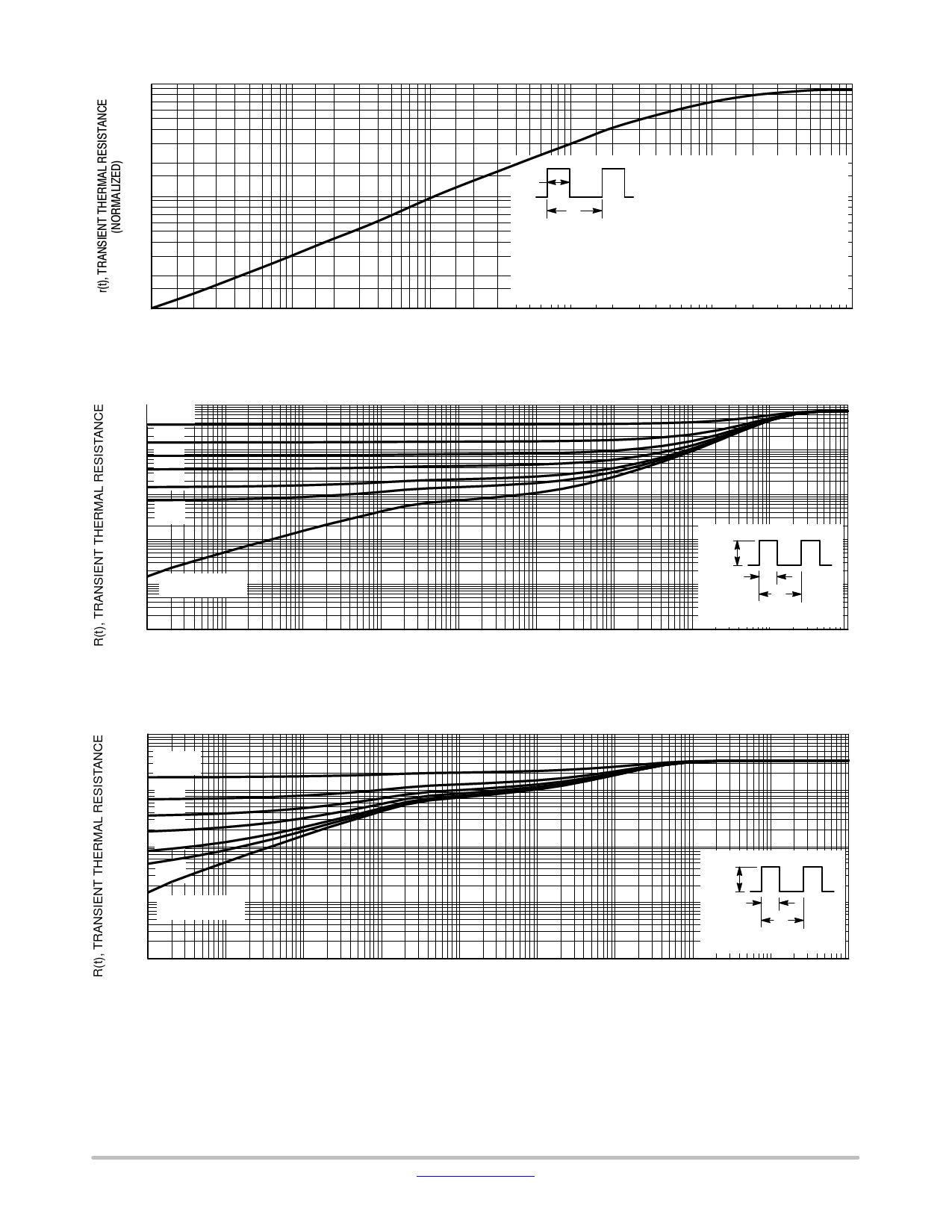
1.0
0.7
0.5
0.3
0.2
0.1
0.07
0.05
0.03
0.02
0.01
0.01
MBR2045CT
Ppk
tp
t1
Ppk
TIME
DUTY CYCLE, D = tp/t1
PEAK POWER, Ppk, is peak of an
equivalent square power pulse.
DTJL = Ppk • RqJL [D + (1 − D) • r(t1 + tp) + r(tp) − r(t1)] where:
DTJL = the increase in junction temperature above the lead temperature.
r(t) = normalized value of transient thermal resistance at time, t, i.e.:
r(t1 + tp) = normalized value of transient thermal resistance at time,
t1 + tp, etc.
0.1
1.0
10
t, TIME (ms)
Figure 9. Thermal Response
100
1000
HIGH FREQUENCY OPERATION
Since current flow in a Schottky rectifier is the result of
majority carrier conduction, it is not subject to junction
diode forward and reverse recovery transients due to minor-
ity carrier injection and stored charge. Satisfactory circuit
analysis work may be performed by using a model consist-
ing of an ideal diode in parallel with a variable capacitance.
(See Figure 10.)
Rectification efficiency measurements show that opera-
tion will be satisfactory up to several megahertz. For exam-
ple, relative waveform rectification efficiency is approxi-
mately 70 percent at 2.0 MHz, e.g., the ratio of dc power to
RMS power in the load is 0.28 at this frequency, whereas
perfect rectification would yield 0.406 for sine wave inputs.
However, in contrast to ordinary junction diodes, the loss in
waveform efficiency is not indicative of power loss; it is
simply a result of reverse current flow through the diode ca-
pacitance, which lowers the dc output voltage.
1000
900
800
700
600
500
400
300
200
100
0
0
TJ = 25°C
f = 1 MHz
10
20
30
40
50
VR, REVERSE VOLTAGE (VOLTS)
Figure 10. Typical Capacitance
+150 V, 10 mAdc
2.0 kW
VCC 12 Vdc
12 V
2.0 ms
1.0 kHz
100
2N2222
CURRENT
AMPLITUDE
ADJUST
0−10 AMPS
100
CARBON
D.U.T.
+
4.0 mF
2N6277
1.0 CARBON
1N5817
Figure 11. Test Circuit for dv/dt and Reverse Surge Current
http://onsemi.com
5
Share Link: 