MAX6864UK29D3S –Я—А–Њ—Б–Љ–Њ—В—А —В–µ—Е–љ–Є—З–µ—Б–Ї–Њ–≥–Њ –Њ–њ–Є—Б–∞–љ–Є—П (PDF) - Maxim Integrated
–Э–Њ–Љ–µ—А –≤ –Ї–∞—В–∞–ї–Њ–≥–µ
–Ъ–Њ–Љ–њ–Њ–љ–µ–љ—В—Л –Ю–њ–Є—Б–∞–љ–Є–µ
–њ—А–Њ–Є–Ј–≤–Њ–і–Є—В–µ–ї—М
MAX6864UK29D3S
Maxim Integrated

MAX6864UK29D3S Datasheet PDF : 17 Pages
| |||
Nanopower µP Supervisory Circuits with
Manual Reset and Watchdog Timer
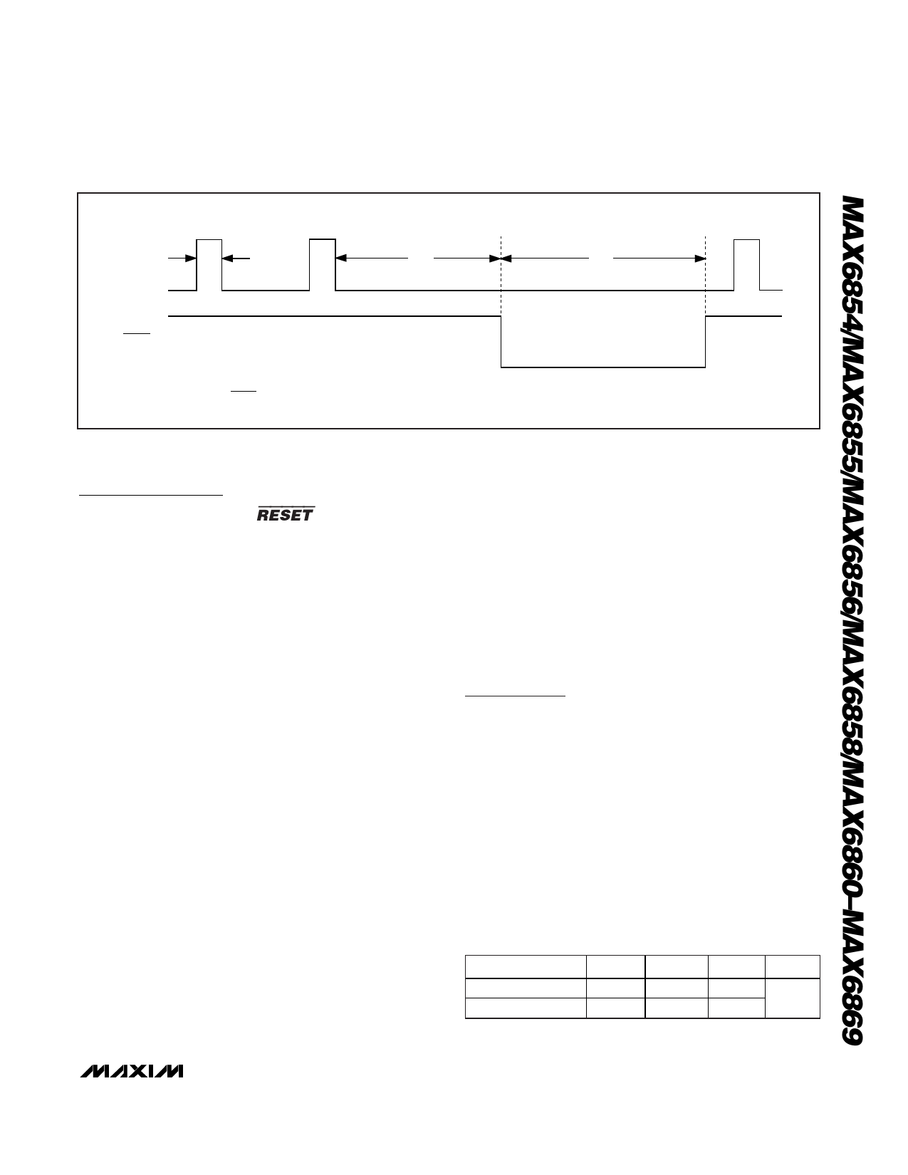
VCC
WDI
tWDI
tWD
tRP
OV
VCC
RESET*
OV
*RESET IS THE INVERSE OF RESET.
Figure 3. Detailed Watchdog Input Timing Relationship
Detailed Description
RESET/RESET Output
A ¬µPвАЩs reset input starts the ¬µP in a known state. The
MAX6854/MAX6855/MAX6856/MAX6858/MAX6860вАУ
MAX6869 µP supervisory circuits assert a reset to prevent
code-execution errors during power-up, power-down, and
brownout conditions. The MAX6854/MAX6855/MAX6856/
MAX6858/MAX6860вАУMAX6869 reset output is guaranteed
to be valid for VCC down to 1.1V.
Whenever VCC falls below the reset threshold, the reset
output asserts low for RESET and high for RESET.
Once VCC exceeds the reset threshold, an internal
timer keeps the reset output asserted for the specified
reset timeout period, then after this interval the reset
output deasserts (see Figure 2).
Manual Reset Input
Many µP-based products require manual reset capabil-
ity, allowing the operator, a test technician, or external
logic circuitry to initiate a reset. The MAX6854/
MAX6855/MAX6856/MAX6861вАУMAX6869 feature an
MR input. A logic low on MR asserts a reset. Reset
remains asserted while MR is low and for the timeout
period, tRP, after MR returns high. The devices provide
an internal 10kвД¶ pullup from MR to VCC. Leave MR
unconnected or connect to VCC if unused. MR can be
driven with CMOS logic levels or with open-drain/col-
lector outputs. Connect a normally open momentary
switch from MR to GND to implement a manual reset
function; external debounce circuitry is not required. If
MR is driven by long cables or the device is used in a
noisy environment, connect a 0.1µF capacitor from MR
to GND to provide additional noise immunity.
Watchdog Input
The MAX6864вАУMAX6869вАЩs watchdog timer circuitry
monitors the ¬µPвАЩs activity. If the ¬µP does not toggle
(low-to-high or high-to-low) the watchdog input (WDI)
within the watchdog timeout period (tWDI), reset asserts
for the reset timeout period (tRP). The internal timer is
cleared when reset asserts, when manual reset is
asserted, or by a rising or falling edge on WDI. The
watchdog input detects pulses as short as 150ns.
While reset is asserted the watchdog timer does not
count. As soon as reset deasserts, the watchdog timer
resumes counting (Figure 3).
Applications Information
Selecting the Reset Timeout Period
The reset timeout period for the MAX6854/MAX6855/
MAX6856/MAX6858/MAX6860/MAX6864вАУMAX6869 is
fixed (see Table 4). The MAX6861/MAX6862/MAX6863
feature a reset timeout select input, CT. Connect CT
according to Table 1 to select between the available
10ms and 150ms (min) reset timeout periods. The time-
out period can be changed while a reset timeout period
is in progress, but will not update until the reset timeout
period has expired.
Table 1. MAX6861/MAX6862/MAX6863
Reset Timeout Period Selection
CT CONNECTION MIN
LOW
10
HIGH
150
TYP
MAX UNITS
15
25
ms
225
300
______________________________________________________________________________________ 11
Share Link: