MAX6323AUT29 Просмотр технического описания (PDF) - Maxim Integrated
Номер в каталоге
Компоненты Описание
производитель
MAX6323AUT29
Maxim Integrated

MAX6323AUT29 Datasheet PDF : 14 Pages
| |||
MAX6323/MAX6324
μP Supervisory Circuits with Windowed
(Min/Max) Watchdog and Manual Reset
VCC
RESET
MR
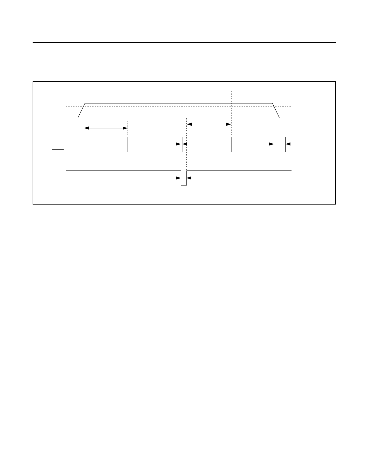
100ms (min)
100ms (min)
120ns (typ)
1µs (min)
VTH
20µs (typ)
Figure 5. RESET Timing Relationship
falls below the preset threshold or when the manual
reset input (MR) is asserted. The RESET output remains
asserted for at least 100ms after VCC has risen above
the reset threshold and MR is deasserted (Figure 5).
For noisy environments, bybass VCC with a 500pF (min)
capacitor to ensure correct operation.
The MAX6323 has a push-pull output stage, and the
MAX6324 utilizes an open-drain output. Connect a
pullup resistor on the RESET output of the MAX6324 to
any supply up to +6V. Select a resistor value large enough
to register a logic low (see Electrical Characteristics) and
small enough to register a logic high while supplying all
input leakage currents and leakage paths connected
to the RESET line. A 10kΩ pullup is sufficient in most
applications.
Manual Reset Input
Many μP-based products require manual reset capability
to allow an operator or external logic circuitry to initiate a
reset. The manual reset input (MR) can connect directly to
a switch without an external pullup resistor or debouncing
network. MR is internally pulled up to VCC and, there-
fore, can be left unconnected if unused. MR is designed
to reject fast, negative-going transients (typically 100ns
pulses), and it must be held low for a minimum of 1μs
to assert the reset output (Figure 5). A 0.1μF capacitor
from MR to ground provides additional noise immunity.
After MR transitions from low to high, reset will remain
asserted for the duration of the reset timeout period, at
least 100ms.
Applications Information
Negative-Going VCC Transients
The MAX6323/MAX6324 are relatively immune to short-
duration negative-going VCC transients (glitches), which
usually do not require the entire system to shut down.
Typically, 200ns large-amplitude pulses (from ground
to VCC) on the supply will not cause a reset. Lower
amplitude pulses result in greater immunity. Typically,
a VCC transient that falls 100mV below the reset
threshold and lasts less than 20μs will not trigger a
reset (see Typical Operating Characteristics). An optional
0.1μF bypass capacitor mounted close to VCC provides
additional transient immunity.
Ensuring a Valid Reset Output
Down to VCC = 0V
When VCC falls below +1.2V, the MAX6323 RESET out-
put no longer sinks current; it becomes an open circuit.
Therefore, high-impedance CMOS logic inputs connected
to RESET can drift to undetermined voltages. This does
not present a problem in most applications, since most
μPs and other circuitry are inoperative with VCC below
+1.2V. However, in applications where RESET must be
valid down to 0, adding a pulldown resistor to RESET
causes any stray leakage currents to flow to ground, hold-
ing RESET low (Figure 6). R1’s value is not critical; 100kΩ
is large enough not to load RESET and small enough to
pull RESET to ground. This scheme does not work with
the open-drain output of the MAX6324.
www.maximintegrated.com
Maxim Integrated │ 9
Share Link: