MAX6323 Просмотр технического описания (PDF) - Maxim Integrated
Номер в каталоге
Компоненты Описание
производитель
MAX6323 Datasheet PDF : 14 Pages
| |||
MAX6323/MAX6324
μP Supervisory Circuits with Windowed
(Min/Max) Watchdog and Manual Reset
POSSIBLE STATES
tWD1 (min)
)
tWD1 (max)
tWD2 (min)
tWD2 (max)
GUARANTEED TO
ASSERT WDPO
GUARANTEED NOT TO
ASSERT WDPO
GUARANTEED TO
ASSERT WDPO
*UNDETERMINED
*UNDETERMINED
CONDITION 1
FAST FAULT
CONDITION 2
NORMAL OPERATION
CONDITION 3
*UNDETERMINED STATES MAY OR MAY NOT GENERATE A FAULT CONDITION.
SLOW FAULT
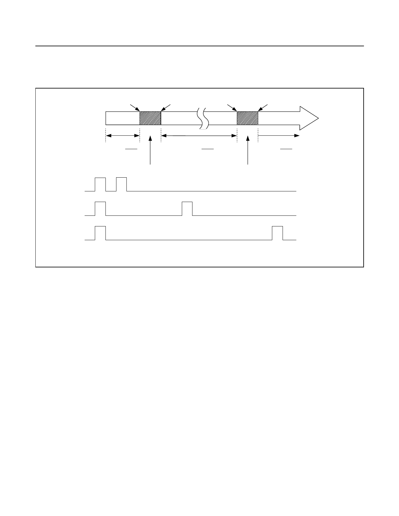
Figure 1. Detailed Watchdog Input Timing Relationship
Detailed Description
The MAX6323/MAX6324 μP supervisory circuits maintain
system integrity by alerting the μP to fault conditions. In
addition to a standard VCC monitor (for power-on reset,
brownout detect, and power-down reset), the devices
include a sophisticated watchdog timer that detects when
the processor is running outside an expected window of
operation for a specific application. The watchdog signals
a fault when the input pulses arrive too early (faster than
the selected tWD1 timeout period) or too late (slower than
the selected tWD2 timeout period) (Figure 1). Incorrect
timing can lead to poor or dangerous system performance
in tightly controlled operating environments. Incorrect
timing could be the result of improper μP clocking or code
execution errors. If a timing error occurs, the MAX6323/
MAX6324 issue a watchdog pulse output, independent
from the reset output, indicating that system maintenance
may be required.
Watchdog Function
A pulse on the watchdog output WDPO can be triggered
by a fast fault or a slow fault. If the watchdog input (WDI)
has two falling edges too close to each other (faster
than tWD1) (Figure 2) or falling edges that are too far
apart (slower than tWD2) (Figure 3), WDPO is pulsed
low. Normal watchdog operation is displayed in Figure 4
(WDPO is not asserted). The internal watchdog timer is
cleared when a WDI falling edge is detected within the
valid watchdog window or when the device’s RESET or
WDPO outputs are deasserted. All WDI input pulses are
ignored while either RESET or WDPO is asserted. Figure
1 identifies the input timing regions where WDPO fault
outputs will be observed with respect to tWD1 and tWD2.
After RESET or WDPO deasserts, the first WDI falling
edge is ignored for the fast fault condition (Figure 2).
Upon detecting a watchdog fault, the WDPO output
will pulse low for 1ms. WDPO is an open-drain output.
Connect a pullup resistor on WDPO to any supply up to
+6V.
VCC Reset
The MAX6323/MAX6324 also include a standard VCC
reset monitor to ensure that the μP is started in a
known state and to prevent code execution errors
during power-up, power-down, or brownout conditions.
RESET is asserted whenever the VCC supply voltage
www.maximintegrated.com
Maxim Integrated │ 7
Share Link: 