MAX2837 Просмотр технического описания (PDF) - Maxim Integrated
Номер в каталоге
Компоненты Описание
производитель
MAX2837 Datasheet PDF : 34 Pages
| |||
MAX2837
2.3GHz to 2.7GHz Wireless
Broadband RF Transceiver
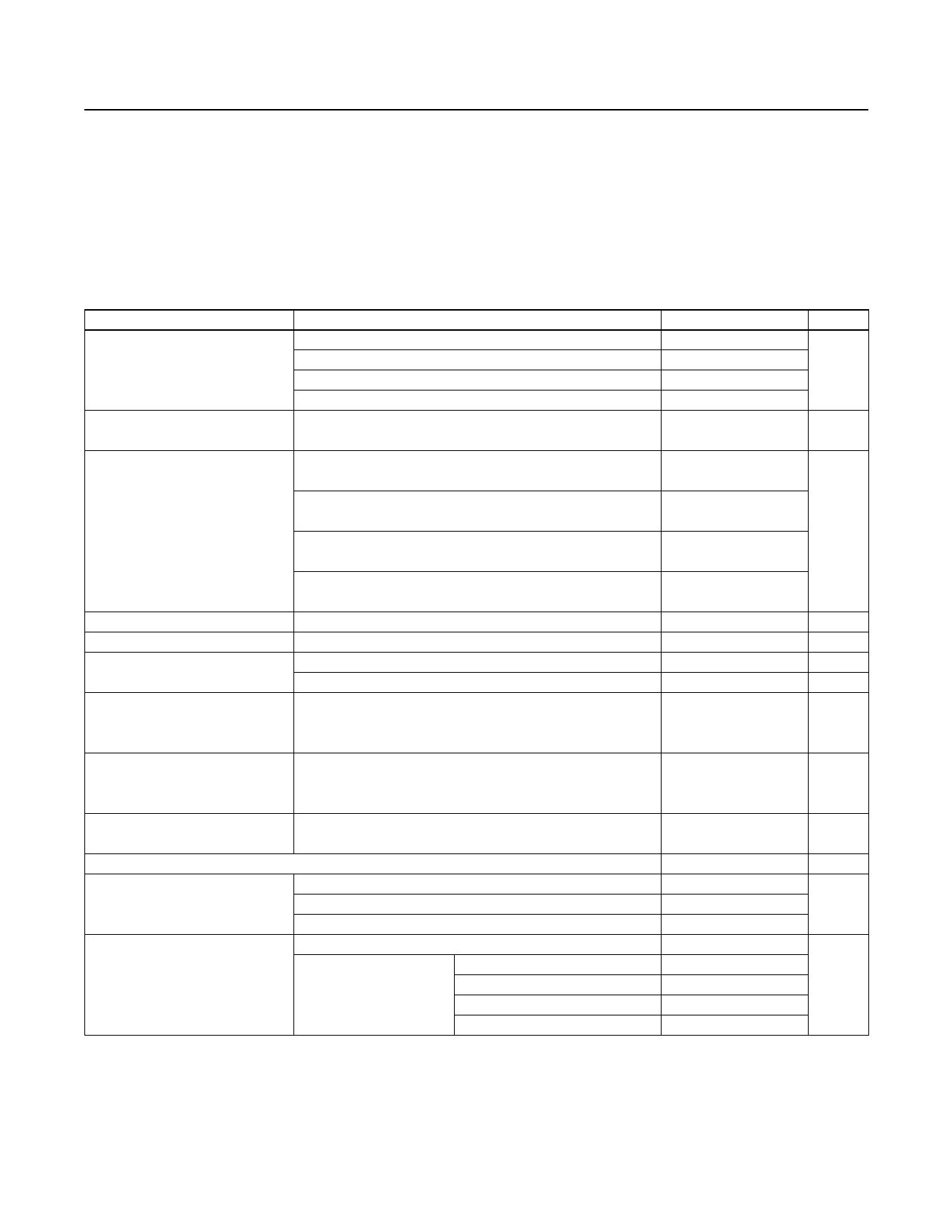
AC Electrical Characteristics—Rx MODE (continued)
(MAX2837 evaluation kit: VCC_ = 2.8V, fRF = 2.502GHz, fLO = 2.5GHz; receiver baseband I/Q outputs at 90mVRMS (-21dBV), fREF
= 40MHz, ENABLE = RXENABLE = CS = high, TXENABLE = SCLK = DIN = low, with power matching for the differential RF pins
using the typical applications and registers set to default settings and corresponding test mode, TA = +25°C, unless otherwise noted.
Lowpass filter is set to 10MHz RF channel BW. Unmodulated single-tone RF input signal is used, unless otherwise indicated.) (Note 1)
PARAMETER
In-Band Input P-1dB
Maximum Output Signal Level
Out-of-Band Input IP3 (Note 2)
I/Q Phase Error
I/Q Gain Imbalance
Rx I/Q Output Load Impedance
(R || C)
I/Q Output DC Droop
CONDITIONS
MIN
Max RF gain (B7:B6 = 00)
Max RF gain - 8dB (B7:B6 = 01)
Max RF gain - 16dB (B7:B6 = 10)
Max RF gain - 32dB (B7:B6 = 11)
Over passband frequency range; at any gain setting; 1dB
compression point
Max RF gain (B7:B6 = 00), AGC set for -65dBm
wanted signal
Max RF gain - 8dB (B7:B6 = 01), AGC set for -55dBm
wanted signal
Max RF gain - 16dB (B7:B6 = 10), AGC set for -40dBm
wanted signal
Max RF gain - 32dB (B7:B6 = 11), AGC set for -30dBm
wanted signal
50kHz baseband output; 1s variation
50kHz baseband output; 1s variation
Minimum differential resistance
Maximum differential capacitance
After switching RXHP to 0; average over 1µs after any gain
change, or 2µs after receive enabled with 100Hz interval AC-
coupling, 1s variation
TYP MAX UNITS
-37
-29
dBm
-21
-4
2.5
VP-P
-11
-8
dBm
-6
+16
0.15
Degrees
0.1
dB
10
kΩ
5
pF
±1
mV/ms
I/Q Static DC Offset
No RF input signal; measure at 3µs after receive enable;
RXHP = 1 for 0 to 2µs and set to 0 after 2µs,
1s variation
±1
mV
Loopback Gain
(for Receiver I/Q Calibration)
Transmitter I/Q input to receiver I/Q output; transmitter B6:B1
= 000011, receiver B5:B1 = 10100 programmed through SPI
-4.5
0
+4.5
dB
RECEIVER BASEBAND FILTERS
At 15MHz
57
Baseband Filter Rejection
At 20MHz
75
dB
At > 40MHz
90
RXHP = 1 (used before AGC completion)
650
Baseband Highpass Filter Corner
Frequency
D5:D4 = 00
RXHP = 0 (used after
AGC completion) address
D5:D4 = 01
A4:A0 = 01110
D5:D4 = 10
D5:D4 = 11
0.1
1
kHz
30
100
www.maximintegrated.com
Maxim Integrated │ 4
Share Link: 