MSM6242B Просмотр технического описания (PDF) - Oki Electric Industry
Номер в каталоге
Компоненты Описание
производитель
MSM6242B Datasheet PDF : 18 Pages
| |||
¡ Semiconductor
MSM6242B
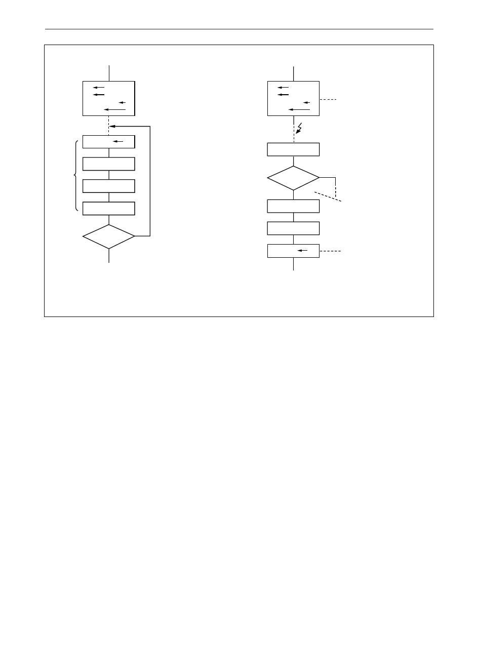
Reading Method 2 when Not Using HOLD Bit
t1 *1
t0 *2
ITRPT/STNT 1
MASK
0
IRQ FLAG 0
Initialization only at power ON
• *1 and *2 represent the minimum required
time out.
For example
t1 = 0 and tO = 1 when required to a
unit of second;
t1 = 1 and tO = 0 when required to a
unit of minute; and
t1 = 1 and tO = 1 when required to a
unit of hour;
See Note
below
WAIT t
TIME DATA READ
REGISTER CD READ
Retried the reading, since a
carry occurred during the
operation.
IRQ FLAG = 0
YES
Normal read
NO
(Note)
Do this process within the following
time requirements by combination
between t1 and t0:
t1 = 0 and tO = 1 . . . Less than 1 second
t1 = 1 and tO = 0 . . . Less than 1 minute
t1 = 1 and tO = 1 . . . Less than 1 hour
t : 12 HOUR MODE . . . 35µS
24 HOUR MODE . . . 3µS
Reading Method 3 when Not Using HOLD Bit
Initialization only at power ON
• *1 and *2 represent the minimum required
t1 *1
t0 *2
ITRPT/STNT 1
MASK
0
time unit.
For example
t1 = 0 and tO = 1 when required to a
unit of second;
t1 = 1 and tO = 0 when required to a
CPU senses the unit of minute; and
interruption. t1 = 1 and tO = 1 when required to a
unit of hour;
REGISTER CD READ
IRQ FLAG = 1
YES
WAIT t
NO
The other IC causes
the interruption.
The interruption is caused by
this IC due to the occurrence
of a carry.
TIME DATA READ
IRQ FLAG 0
The IRQ FLAG is cleared to
read the next time data.
END
CD REGISTER (Control D Register)
a) HOLD (D0) –
Setting this bit to a "1" inhibits the 1Hz clock to the S1 counter, at which
time the Busy status bit can be read. When Busy = 0, register's S1 ~ W
can be read or written. During this procedure if a carry occurs the S1
counter will be incremented by 1 second after HOLD = 0 (this condition
is guaranteed as long as HOLD = 1 does not exceed 1 second in
duration). If CS1 = 0 then HOLD = 0 irrespective of any condition.
b) BUSY (D1) –
Status bit which shows the interface condition with microcontroller/
microprocessors. As for the method of writing into and reading from
S1 ~ W (address φ ~ C), refer to the flow chart described in Figure 10.
c) IRQ FLAG (D2) – This status bit corresponds to the output level of the STD.P output.
When STD.P = 0, then IRQ = 1; when STD.P = 1, then IRQ = 0. The IRQ
FLAG indicates that an interrupt has occurred to the microcomputer if
IRQ = 1. When D0 of register CE (MASK) = 0, then the STD.P output
changes according to the timing set by D3 (t1) and D2 (t0) of register E.
When D1 of register E (ITRPT/STND) = 1 (interrupt mode), the STD.P
output remains low until the IRQ FLAG is written to a "0". When IRQ
= 1 and timing for a new interrupt occurs, the new interrupt is ignored.
When ITRPT/STND = 0 (Standard Pulse Output mode) the STD.P
output remains low until either "0" is written to the IRQ FLAG;
otherwise, the IRQ FLAG automatically goes to "0" after 7.8125ms.
When writing the HOLD or 30 second adjust bits of register D, it is
necessary to write the IRQ FLAG bit to a "1".
d) ±30 ADJ (D3) – When 30-second adjustment is necessary, a "1" is written to bit D3
during which time the internal clock registers should not be read from
or written to 125µs after bit D3 = 1 it will automatically return to a "0",
and at that time reading or writing of registers can occur.
33
Share Link: 