M54670P Просмотр технического описания (PDF) - Mitsumi
Номер в каталоге
Компоненты Описание
производитель
M54670P Datasheet PDF : 6 Pages
| |||
MITSUBISHI <CONTROL / DRIVER IC>
M54670P
2-PHASE STEPPER MOTOR DRIVER
APPLICATION DESCRIPTION
(1) PHASE INPUT
Phase input decides the output mode.
PHASE
O1
O2
H
L
H
L
H
L
(2) I0, I1
I0 and I1 fixed based on the comparative voltage VR decide the
output current level.
I0
I1
Current level
H
H
0
L
H
Low
H
L
Typ
L
L
High
(3) VR (Comparative voltage)
The current level can be continuously changed by changing the
voltage at VR continuously.
(4) Current sensor
When the voltage fall at the current sensing resistor and the
selected current level become of the same level, the output
state is cut off for a certain time by inverting the comparator.
During this cutoff time, the current volume decreases slightly
due to the L component of the motor and falls short of the
comparative level. During the time fixed based on the PWM
frequency, the output stage goes in ON state and then in OFF
state and this ON/OFF operation is repeated.
(5) PWM oscillator
A capacitor Cf is externally connected to CT pin in order to fix
the PWM oscillator frequency. The frequency fc is calculated as
follows.
1
fc =
7.77 x 10³ x Cf
(6) Analog control
The output current level can be continuously changed by
changing the voltage at VR or the feedback voltage to the
comparator.
(7) Thermal shutdown function
This IC has a function to protect itself against thermal damage
which is caused when the chip temperature rises abnormally.
Regarding this function, refer to “PRECAUTIONS FOR USE.”
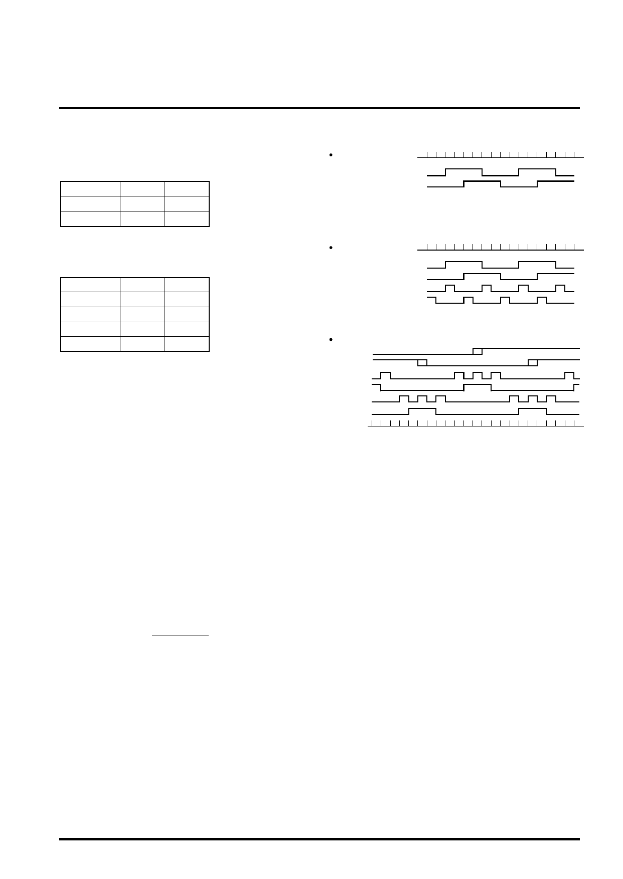
TIMING CHART
2-phase excitation
Phase 1
Phase 2
I0, 1(A) = 0
I0, 1(B) = 0
1-2-phase excitation
Phase 1
Phase 2
I0, 1(A)
I0, 1(B)
Microstep
Phase 1
Phase 2
I0(A)
I1(A)
I0(B)
I1(B)
Share Link: 