LX1744 Просмотр технического описания (PDF) - Microsemi Corporation
Номер в каталоге
Компоненты Описание
производитель
LX1744 Datasheet PDF : 16 Pages
| |||
INTEGRATED PRODUCTS
LX1744
Dual Output Boost – LED Driver / LCD Bias
PRODUCTION DATASHEET
APPLICATION NOTE
less than 100kHz, an external filter capacitor will be
needed (Figure 5). The value of CPWM is easily calculated
based on the PWM frequency and RPWM_1 using the
following equation.
CPWM
=
50
π ⋅ fPWM ⋅ RPWM _1
eq. 3
where
RPWM _1 << 2.5MΩ
eq. 4
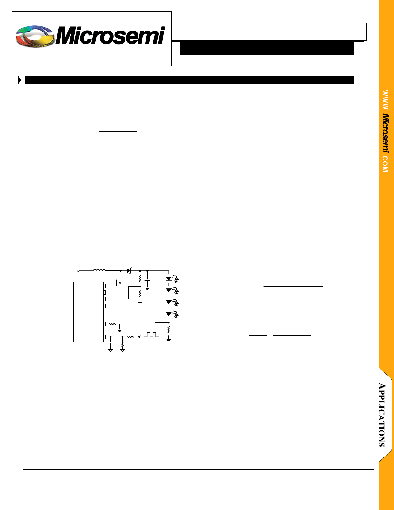
LED DRIVER – OUTPUT CURRENT PROGRAMMING
Maximum LED current is easily programmed by
choosing the appropriate value for RLED (Figure 6). It is
recommended that a minimum value of 15Ω be used for
this resistor in order to prevent noise coupling issues on the
feedback line. Although, alternate values can be calculated
using the following equation:
300mV (VBRT) be used in order to minimize dissipative
losses in the LED current sense resistor (RLED).
Like the LCD bias adjustment (ADJ) pin, the BRT pin is
connected to an internal 50pF capacitor to ground that
works with an external resistor to create a low-pass filter,
allowing the BRT pin to driven directly by a PWM signal
whose frequency is greater than 100kHz. When this pin is
driven by a PWM signal whose frequency is less than
100kHz, an external filter capacitor is needed. This
capacitor is selected such that the ripple component of the
resultant voltage on the BRT pin is less than 10% of the
nominal input voltage.
For PWM frequencies greater than 100kHz, the external
BRT input resistor is calculated using the following
equation.
RBRT _1
=
2.5MΩ
⋅
⎜⎜⎝⎛
VPWM (DCMAX ) − VBRT(MAX)
VBRT(MAX)
⎟⎟⎠⎞
eq. 6
VBAT = 1.6V to 6.0V
VBRT(MAX)
R = LED
ILED(MAX)
L1
DRV
SRC
OVP
D1
ROVP_1
ROVP_2
C1
4.7µF
where VBRT is the selected maximum LED current sense
eq. 5 feedback threshold.
For PWM frequencies less than 100kHz, the external
BRT input resistors and filter capacitor (Figure 4) are
calculated using the following equations.
RBRT _1
=
RBRT _ 2
⋅
⎜⎜⎝⎛
VPWM (DCMAX ) − VBRT(MAX)
VBRT(MAX)
⎟⎟⎠⎞
eq. 7
LFB
LX1744
CS
BRT
RCS
RBRT_1
CBRT
RBRT_2
where RBRT_2 is selected and VBRT(MAX) is the selected
maximum LED current sense feedback threshold.
RLED
15Ω
CBRT
=
5
π ⋅ fPWM
⋅
⎜⎜⎝⎛
RBRT _1 + RBRT _ 2
RBRT _1 ⋅ RBRT _ 2
⎟⎟⎠⎞
eq. 8
Figure 6 – LED Current Programming
LED DRIVER – LED BRIGHTNESS ADJUSTMENT
The LX1744 features a full range dimming LED driver.
LED current regulation is accomplished by using the
applied BRT pin voltage as the LED current reference.
This reference voltage, in conjunction with the LED current
setting resistor (RLED), sets the LED output current.
Dimming can be accomplished in one of two ways: by
applying a variable DC voltage, or by varying the duty
cycle (DC) of a PWM control signal, directly to the BRT
pin.
It is recommended that a maximum signal voltage of
where VRIPPLE is selected to be 10% of VBRT, and fPWM is
the PWM signal frequency.
DIODE SELECTION
A Schottky diode is recommended for most applications
(e.g. Microsemi UPS5817). The low forward voltage drop
and fast recovery time associated with this device supports
the switching demands associated with this circuit
topology. The designer is encouraged to consider the
diode’s average and peak current ratings with respect to the
application’s output and peak inductor current
requirements. Further, the diode’s reverse breakdown
voltage characteristic must be capable of withstanding a
Copyright © 2000
Rev. 1.1b, 2005-03-01
Microsemi
Integrated Products Division
11861 Western Avenue, Garden Grove, CA. 92841, 714-898-8121, Fax: 714-893-2570
Page 8
Share Link: 