LTC4101 Просмотр технического описания (PDF) - Linear Technology
Номер в каталоге
Компоненты Описание
производитель
LTC4101 Datasheet PDF : 30 Pages
| |||
LTC4101
OPERATION
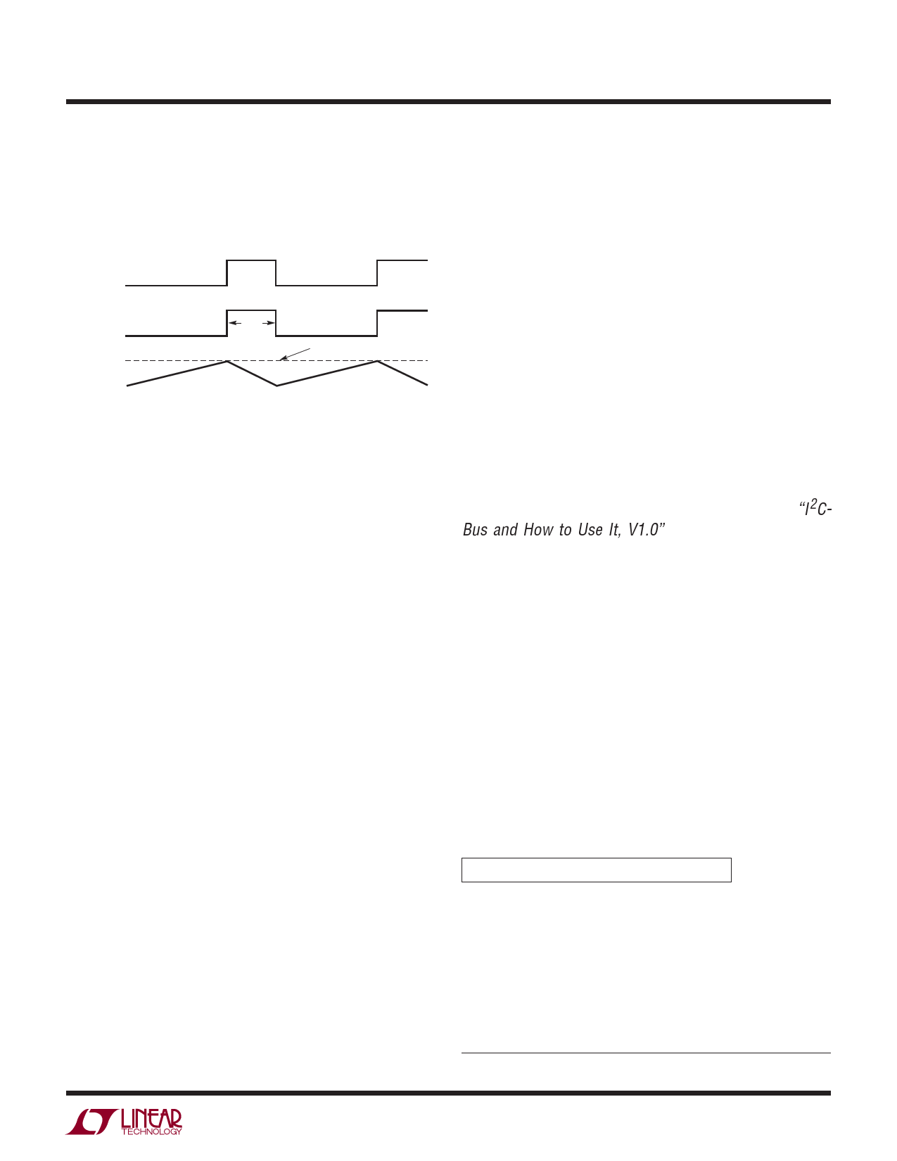
to set the bottom MOSFET on time. The result is quasi-
constant frequency operation: the converter frequency
remains nearly constant over a wide range of output
voltages. This activity is diagrammed in Figure 3.
OFF
TGATE
ON
ON
BGATE
OFF
INDUCTOR
CURRENT
tOFF
Figure 3.
TRIP POINT SET
BY ITH VOLTAGE
4101 F01
The peak inductor current, at which ICMP resets the SR
latch, is controlled by the voltage on ITH. ITH is in turn
controlled by several loops, depending upon the situation
at hand. The average current control loop converts the
voltage between CSP and BAT to a representative current.
Error amp CA2 compares this current against the desired
current programmed by the IDAC at the IDC pin and adjusts
ITH for the desired voltage across RSENSE.
The voltage at BAT is divided down by an internal resis-
tor divider set by the VDAC and is used by error amp EA
to decrease ITH if the divider voltage is above the 1.19V
reference.
The amplifier CL1 monitors and limits the input current,
normally from the AC adapter, to a preset level (100mV/RCL).
At input current limit, CL1 will decrease the ITH voltage to
reduce charging current.
An overvoltage comparator, OV, guards against transient
overshoots (>7%). In this case, the top MOSFET is turned
off until the overvoltage condition is cleared. This feature
is useful for batteries that “load dump” themselves by
opening their protection switch to perform functions such
as calibration or pulse mode charging.
PWM Watchdog Timer
There is a watchdog timer that observes the activity on the
TGATE pin. If TGATE stops switching for more than 40μs,
the watchdog activates and turns off the top MOSFET for
about 400ns. The watchdog engages to prevent very low
frequency operation in dropout – a potential source of audible
noise when using ceramic input and output capacitors.
Charger Start-Up
When the charger is enabled, it will not begin switching
until the ITH voltage exceeds a threshold that assures initial
current will be positive. This threshold is 5% to 15% of the
maximum programmed current. After the charger begins
switching, the various loops will control the current at a
level that is higher or lower than the initial current. The
duration of this transient condition depends upon the loop
compensation, but is typically less than 1ms.
SMBus Interface
All communications over the SMBus are interpreted by the
SMBus interface block. The SMBus interface is a SMBus
slave device at address 0x12. All internal LTC4101 reg-
isters may be updated and accessed through the SMBus
interface, and charger controller as required. The SMBus
protocol is a derivative of the I2C bus (Reference “I2C-
Bus and How to Use It, V1.0” by Philips, and “System
Management Bus Specification,” Version 1.1, from the
SBS Implementers Forum, for a complete description of
the bus protocol requirements.)
All data is clocked into the shift register on the rising edge
of SCL. All data is clocked out of the shift register on the
falling edge of SCL. Detection of an SMBus Stop condi-
tion, or power-on reset via the VDD power-fail, will reset
the SMBus interface to an initial state at any time.
The LTC4101 command set is interpreted by the SMBus
interface and passed onto the charger controller block as
control signals or updates to internal registers.
Description of Supported Battery Charger Functions
The functions are described as follows (see Table 1 also):
FunctionName() 'hnn (command code)
Description: A brief description of the function.
Purpose: The purpose of the function, and an example
where appropriate.
• SMBus Protocol: Refer to Section 5 of the Smart
Battery Charger specification for more details.
*http://www.SBS-FORUM.org
4101fa
11
Share Link: 