LTC2930H Просмотр технического описания (PDF) - Linear Technology
Номер в каталоге
Компоненты Описание
производитель
LTC2930H Datasheet PDF : 12 Pages
| |||
LTC2930
ABSOLUTE MAXIMUM RATINGS
(Notes 1, 2, 3)
V1, V2, V3, V4, V5, V6, VPG, RST................ –0.3V to 7V
CRT, VREF, MR...............................–0.3V to (VCC + 0.3V)
Reference Load Current (IVREF)..............................±1mA
V4 Input Current (–ADJ Mode) ..............................–1mA
RST Current .........................................................±10mA
Operating Temperature Range
LTC2930C ................................................ 0°C to 70°C
LTC2930I.............................................. –40°C to 85°C
LTC2930H .......................................... –40°C to 125°C
Storage Temperature Range................... –65°C to 150°C
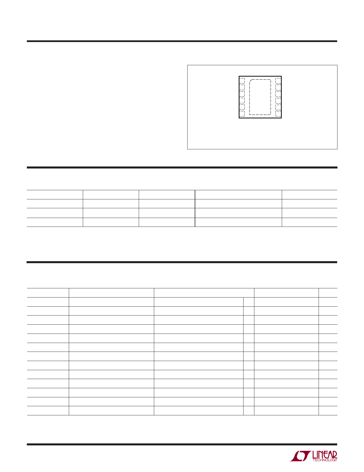
PIN CONFIGURATION
TOP VIEW
V5 1
V3 2
V1 3
CRT 4
RST 5
MR 6
12 V6
11 V2
13
10 V4
9 VREF
8 VPG
7 GND
DD PACKAGE
12-LEAD (3mm × 3mm) PLASTIC DFN
TJMAX = 130°C, θJA = 43°C/W
EXPOSED PAD (PIN 13) IS GND
(PCB CONNECTION OPTIONAL)
ORDER INFORMATION
LEAD FREE FINISH
TAPE AND REEL
PART MARKING*
PACKAGE DESCRIPTION
LTC2930CDD#PBF
LTC2930CDD#TRPBF LDMJ
12-Lead 3mm × 3mm DFN
LTC2930IDD#PBF
LTC2930IDD#TRPBF
LDMJ
12-Lead 3mm × 3mm DFN
LTC2930HDD#PBF
LTC2930HDD#TRPBF LDMJ
12-Lead 3mm × 3mm DFN
*The temperature grade is identified by a label on the shipping container.
For more information on lead free part marking, go to: http://www.linear.com/leadfree/
This product is only offered in trays. For more information go to: http://www.linear.com/packaging/
TEMPERATURE RANGE
0°C to 70°C
–40°C to 85°C
–40°C to 125°C
ELECTRICAL CHARACTERISTICS The ● denotes the specifications which apply over the full operating
temperature range, otherwise specifications are at TA = 25°C. VCC = 5V, unless otherwise specified. (Note 3)
SYMBOL
VCC
VCCMINP
VRT50
VRT33
VRT30
VRT25
VRT18
VRT15
VRTA
VRTAN
VREF
VPG
IVPG
PARAMETER
Minimum Internal Operating Voltage
CONDITIONS
RST in Correct Logic State
MIN
●
Minimum Required for Mode Selection VCC Rising
5V, 5% Reset Threshold
V1 Input Threshold
●
● 4.600
3.3V, 5% Reset Threshold
V1, V2 Input Threshold
● 3.036
3V, 5% Reset Threshold
V2 Input Threshold
● 2.760
2.5V, 5% Reset Threshold
V2, V3 Input Threshold
● 2.300
1.8V, 5% Reset Threshold
V3, V4 Input Threshold
● 1.656
1.5V, 5% Reset Threshold
V3, V4 Input Threshold
● 1.380
ADJ Reset Threshold
V3, V4, V5, V6 Input Threshold
● 492.5
–ADJ Reset Threshold
V4 Input Threshold
● –18
Reference Voltage
Mode Selection Voltage Range
VPG Input Current
VCC ≥ 2.3V, IVREF = ±1mA, CREF ≤ 1000pF ● 1.192
VCC ≥ VCCMINP
●
0
VPG = VREF
●
TYP
4.675
3.086
2.805
2.338
1.683
1.403
500
0
1.210
MAX
1
2.4
4.750
3.135
2.850
2.375
1.710
1.425
507.5
18
1.228
VREF
±20
UNITS
V
V
V
V
V
V
V
V
mV
mV
V
V
nA
2930fa
2
Share Link: 