LTC1544 Просмотр технического описания (PDF) - Linear Technology
Номер в каталоге
Компоненты Описание
производитель
LTC1544 Datasheet PDF : 20 Pages
| |||
LTC1544
APPLICATIONS INFORMATION
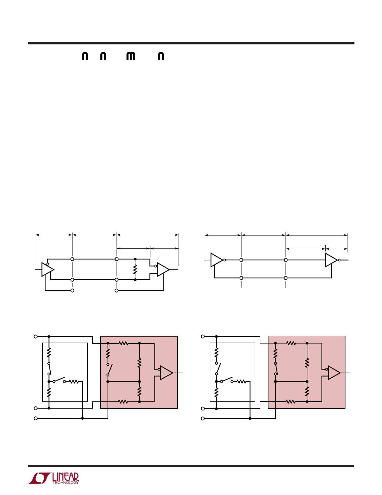
V.11 (RS422) Interface
A typical V.11 balanced interface is shown in Figure 14. A
V.11 differential generator with outputs A and B with
ground C is connected to a differential receiver with
ground C', inputs A' connected to A, B' connected to B. The
V.11 interface has a differential termination at the receiver
end that has a minimum value of 100Ω. The termination
resistor is optional in the V.11 specification, but for the
high speed clock and data lines, the termination is required
to prevent reflections from corrupting the data. The
receiver inputs must also be compliant with the imped-
ance curve shown in Figure 12.
In V.11 mode, all switches are off except S1 inside the
LTC1344A which connects a 103Ω differential termina-
tion impedance to the cable as shown in Figure 15.
V.28 (RS232) Interface
A typical V.28 unbalanced interface is shown in Figure 16.
A V.28 single-ended generator output A with ground C is
connected to a single-ended receiver with input A' con-
nected to A, ground C' connected via the signal return
ground C.
In V.28 mode all switches are off except S3 inside the
LTC1543/LTC1544 which connects a 6k (R8) impedance
to ground in parallel with 20k (R5) plus 10k (R6) for a
combined impedance of 5k as shown in Figure 17. The
noninverting input is disconnected inside the LTC1543/
LTC1544 receiver and connected to a TTL level reference
voltage for a 1.4V receiver trip point.
GENERATOR
BALANCED
INTERCONNECTING
CABLE
LOAD
CABLE
TERMINATION
RECEIVER
A
A'
100Ω
MIN
B
B'
C
C'
1544 F14
Figure 14. Typical V.11 Interface
GENERATOR
BALANCED
INTERCONNECTING
CABLE
LOAD
CABLE
TERMINATION
RECEIVER
A
A'
C
C'
1544 F16
Figure 16. Typical V.28 Interface
A'
A
R1 LTC1344A
51.5Ω
R5
R8 20k
6k
S1
R3
S3
S2 124Ω
R2
51.5Ω
B'
C'
R4
B
20k
GND
LTC1543
LTC1544
R6 RECEIVER
10k
R7
10k
1544 F15
Figure 15. V.11 Receiver Configuration
A'
A
R1 LTC1344A
51.5Ω
R8
R5
20k
6k
S1
S3
R3
S2 124Ω
R2
51.5Ω
B'
C'
R4
B
20k
GND
LTC1543
LTC1544
R6
10k
RECEIVER
R7
10k
1544 F17
Figure 17. V.28 Receiver Configuration
11
Share Link: 