LT1121IS8-PBF Просмотр технического описания (PDF) - Linear Technology
Номер в каталоге
Компоненты Описание
производитель
LT1121IS8-PBF Datasheet PDF : 16 Pages
| |||
LT1121/LT1121-3.3/LT1121-5
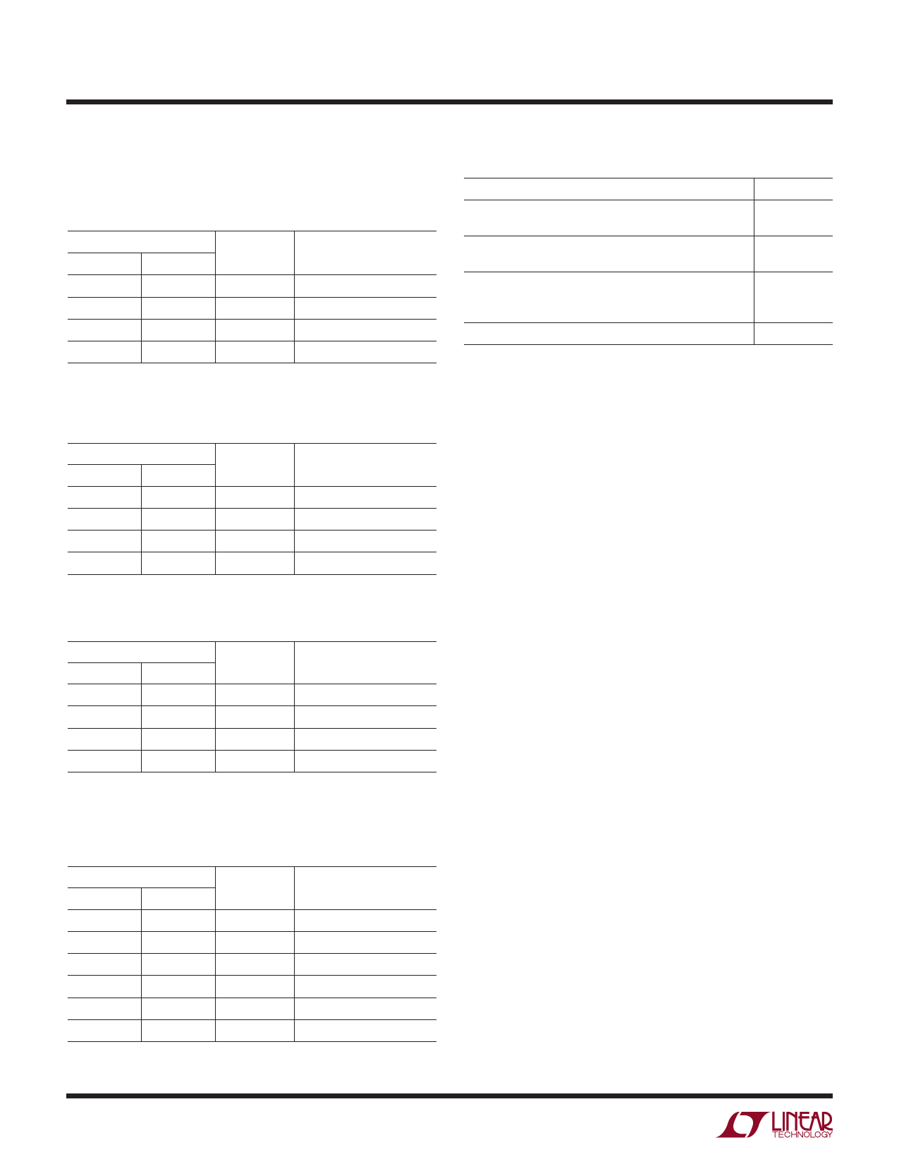
APPLICATIONS INFORMATION
NC leads were connected to the ground plane.
Table 1. N8 Package*
COPPER AREA
THERMAL RESISTANCE
TOPSIDE BACKSIDE BOARD AREA JUNCTION TO AMBIENT
2500 sq mm 2500 sq mm 2500 sq mm
80ºC/W
1000 sq mm 2500 sq mm 2500 sq mm
80ºC/W
225 sq mm 2500 sq mm 2500 sq mm
85ºC/W
1000 sq mm 1000 sq mm 1000 sq mm
91ºC/W
* Device is mounted on topside. Leads are through hole and are
soldered to both sides of board.
Table 2. S8 Package
COPPER AREA
TOPSIDE* BACKSIDE BOARD AREA
2500 sq mm 2500 sq mm 2500 sq mm
1000 sq mm 2500 sq mm 2500 sq mm
225 sq mm 2500 sq mm 2500 sq mm
100 sq mm 1000 sq mm 1000 sq mm
* Device is mounted on topside.
THERMAL RESISTANCE
JUNCTION TO AMBIENT
120ºC/W
120ºC/W
125ºC/W
131ºC/W
Table 3. AS8 Package*
COPPER AREA
TOPSIDE** BACKSIDE BOARD AREA
2500 sq mm 2500 sq mm 2500 sq mm
1000 sq mm 2500 sq mm 2500 sq mm
225 sq mm 2500 sq mm 2500 sq mm
100 sq mm 2500 sq mm 2500 sq mm
* Pins 3, 6 and 7 are ground.
** Device is mounted on topside.
THERMAL RESISTANCE
JUNCTION TO AMBIENT
60ºC/W
60ºC/W
68ºC/W
74ºC/W
Table 4. SOT-223 Package
(Thermal Resistance Junction-to-Tab 20ºC/W)
COPPER AREA
THERMAL RESISTANCE
TOPSIDE* BACKSIDE BOARD AREA JUNCTION TO AMBIENT
2500 sq mm 2500 sq mm 2500 sq mm
50ºC/W
1000 sq mm 2500 sq mm 2500 sq mm
50ºC/W
225 sq mm 2500 sq mm 2500 sq mm
58ºC/W
100 sq mm 2500 sq mm 2500 sq mm
64ºC/W
1000 sq mm 2500 sq mm 1000 sq mm
57ºC/W
1000 sq mm
0
1000 sq mm
60ºC/W
* Tab of device attached to topside copper.
10
Table 5. TO-92 Package THERMAL RESISTANCE
Package alone
Package soldered into PC board with plated through
holes only
Package soldered into PC board with 1/4 sq. inch of
copper trace per lead
Package soldered into PC board with plated through
holes in board, no extra copper trace, and a clip-on type
heat sink: Thermalloy type 2224B
Aavid type 5754
220ºC/W
175ºC/W
145ºC/W
160ºC/W
135ºC/W
Calculating Junction Temperature
Example: given an output voltage of 3.3V, an input voltage
range of 4.5V to 7V, an output current range of 0mA to
100mA, and a maximum ambient temperature of 50°C,
what will the maximum junction temperature be?
Power dissipated by the device will be equal to:
IOUT MAX • (VIN MAX – VOUT) + (IGND • VIN)
where, IOUT MAX = 100mA
VIN MAX = 7V
IGND at (IOUT = 100mA, VIN = 7V) = 5mA
so, P = 100mA • (7V – 3.3V) + (5mA • 7V)
= 0.405W
If we use an SOT-223 package, then the thermal resistance
will be in the range of 50°C/W to 65°C/W depending on
copper area. So the junction temperature rise above ambi-
ent will be less than or equal to:
0.405W • 60°C/W = 24°C
The maximum junction temperature will then be equal to
the maximum junction temperature rise above ambient
plus the maximum ambient temperature or:
TJMAX = 50°C + 24°C = 74°C
Output Capacitance and Transient Performance
The LT1121 is designed to be stable with a wide range of
output capacitors. The minimum recommended value is 1µF
with an ESR of 3Ω or less. For applications where space
is very limited, capacitors as low as 0.33µF can be used if
combined with a small series resistor. Assuming that the
ESR of the capacitor is low (ceramic) the suggested series
1121fg
Share Link: 