LT1469CDF-PBF(RevA) –Я—А–Њ—Б–Љ–Њ—В—А —В–µ—Е–љ–Є—З–µ—Б–Ї–Њ–≥–Њ –Њ–њ–Є—Б–∞–љ–Є—П (PDF) - Linear Technology
–Э–Њ–Љ–µ—А –≤ –Ї–∞—В–∞–ї–Њ–≥–µ
–Ъ–Њ–Љ–њ–Њ–љ–µ–љ—В—Л –Ю–њ–Є—Б–∞–љ–Є–µ
–њ—А–Њ–Є–Ј–≤–Њ–і–Є—В–µ–ї—М
LT1469CDF-PBF Datasheet PDF : 20 Pages
| |||
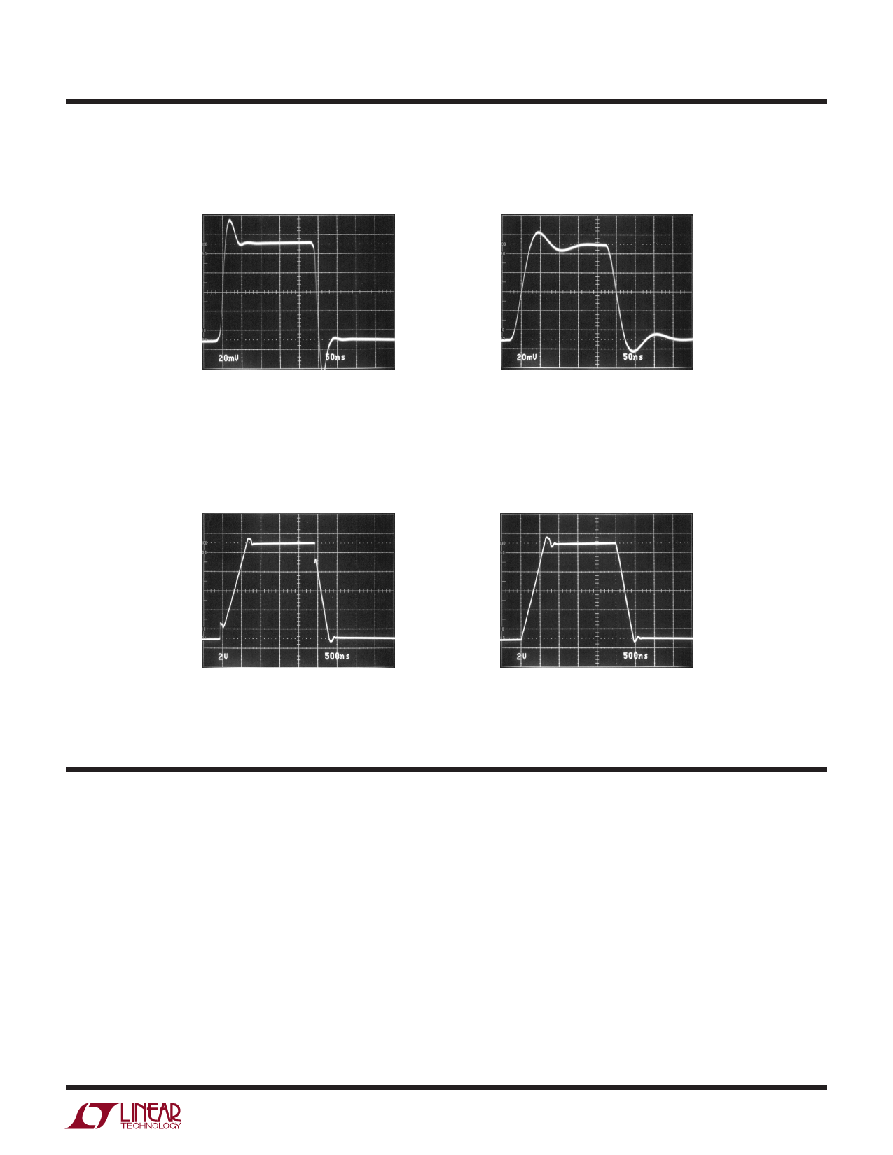
TYPICAL PERFORMANCE CHARACTERISTICS
Small-Signal Transient, AV = 1
Small-Signal Transient, AV = вАУ 1
LT1469
VS = ±15V
1469 G37
VS = ±15V
1469 G38
Large-Signal Transient, AV = 1
Large-Signal Transient, AV = вАУ 1
VS = ±15V
1469 G39
VS = ±15V
1469 G40
APPLICATIONS INFORMATION
Layout and Passive Components
The LT1469 requires attention to detail in board layout
in order to maximize DC and AC performance. For best
AC results (for example, fast settling time) use a ground
plane, short lead lengths and RF quality bypass capacitors
(0.01ќЉF to 0.1ќЉF) in parallel with low ESR bypass capaci-
tors (1ќЉF to 10ќЉF tantalum). For best DC performance, use
вАЬstarвАЭ grounding techniques, equalize input trace lengths
and minimize leakage (e.g., 1.5Gќ© of leakage between an
input and a 15V supply will generate 10nAвАФequal to the
maximum IBвАУ speciпђБcation).
Board leakage can be minimized by encircling the input
circuitry with a guard ring operated at a potential close
to that of the inputs: for inverting conпђБgurations tie the
ring to ground, in noninverting connections tie the ring
to the inverting input (note the input capacitance will
increase which may require a compensating capacitor as
discussed below).
Microvolt level error voltages can also be generated in
the external circuitry. Thermocouple effects caused by
temperature gradients across dissimilar metals at the
contacts to the inputs can exceed the inherent drift of
1469fa
11
Share Link: 