LS7631 Просмотр технического описания (PDF) - LSI Corporation
Номер в каталоге
Компоненты Описание
производитель
LS7631 Datasheet PDF : 4 Pages
| |||
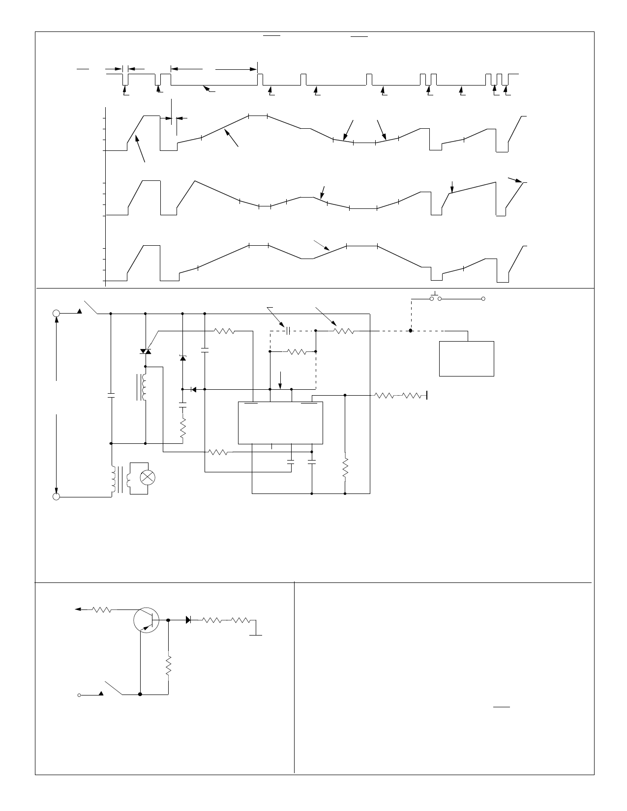
FIGURE 4. LS7632 TRIG, Ø vs TOUCH (SENS OR EXT)
SENS
TS1
TS2
SHORT SHORT
LONG
LONG
LONG
LONG
SHORT LONG
SHORT
150º
Ø 100º
MODE Ø 50º
OFF
150º
Ø 100º
MODE 1 50º
OFF
342ms
A2
SLOPE = SS
A0 A0
SLOPE = SAA
A1 B1 B2 A2
SLOPE = SBA
A1 B1
B2
A2
REVERSE
A1
B1
A2
B2
A2
MEMORY
MEMORY
150º
Ø 100º
MODE 2 50º
OFF
P
REVERSE
A0 A0
A0
A0
A2
FIGURE 6. A Typical Halogen Lamp Dimmer Wall Switch
SEE NOTE 2
G
R8
C6
R7
EXTN
A2
P
MT1
T
MT2
+
C5
Z-
R3
SEE NOTE 3
ELECTRONIC
EXTENSION
(FIG. 7)
115VAC
OR
C1
220VAC
SEE
NOTE 4
N
D1
L
C2
R1
R2
LAMP
87 6
5
TRIG V SS EXT S E N S
LS7631/LS7632
V DD MODE CAP SYNC
123 4
C3 C4
R6
R5
TOUCH
PLATE
NOTES
1. All circuits connected by broken lines are optional.
2. C6 is used only with electronic extension
and R7 is used only with a pushbutton.
3. Connection between Pin 6 & Pin 7 should
R4
be broken when EXT is used.
4. As a precaution, transformer should have
thermal protection.
C1 = 0.15µF, 200V
* C1 = 0.15µF, 400V
C2 = 0.15µF, 200V
* C2 = 0.082µF, 400V
C3 = 0.02µF, 12V
C4 = 0.002µF, 12V
* = component change for 220VAC
C5 = 100µF, 12V
C6 = 0.1µF, 12V
R1 = 270Ω, 1/2W
* R1 = 1kΩ, 1W
R2 = 680Ω, 1/4W
* R2 = 1.5MΩ, 1/4W
R3 = 1.5MΩ, 1/4W
FIGURE 7. ELECTRONIC EXTENSION
MPS8599
EXT
IN914 *R
*R
10k Ω
TOUCH PLATE
200k Ω
*R = 2M Ω for 115VAC
*R = 3.6M Ω for 220VAC
All Resistors 1/4W
P
EXTENSIONS: All switching and dimming functions can be
implemented by utilizing the EXT input. Use a pushbutton or
the electronic switch in conjunction with a Touch Plate as
shown in Figure 7. When the plate is touched, a logic high
level is generated at the EXT input of the IC for both half-
cycles of the line frequency. (See Figure 6)
7631/32-112102-4
R4 = 1MΩ to 5MΩ, 1/4W
(Select for Sensitivity)
R5, R6 = 2.7MΩ, 1/4W
* R5, R6 = 4.7MΩ, 1/4W
R7 = 150kΩ, 1/4W
R8 = 62Ω, 1/4W
D1 = 1N4148
Z = 5.6V, 1W (Zener)
T = Q4004L4 Typical Triac (1)
* T = Q5003L4 Typical Triac (1)
L = 100µH (RFI Filter)
* L = 200µH (RFI Filter)
(1) For loads greater than 6A,
use an alternistor
.
APPLICATION EXAMPLE:
A typical implementation of the light dimmer circuit is shown in Fig. 6.
Here the brightness of the lamp is set by touching the touch plate.
The function of different components are as follows:
• The 5V DC supply for the chip is provided by Z, D1, R1, C2 and C5.
• R2 and C4 generate the filtered signal for the SYNC input
for synchronizing the internal PLL with the line frequency.
• R3 and C6 act as a filter circuit for the electronic extension.
If extensions are not used, the EXT input (Pin 6) should be
tied to Vss (Pin 7).
• R4, R5 and R6 set up the sensitivity of the SENS input.
• C3 is the filter capacitor for the internal PLL.
• R8 provides current limiting and isolation between the chip
output and the triac gate.
• C1 and L are RFI filter circuits.
Share Link: 