LH1901-2R Просмотр технического описания (PDF) - Power-One Inc.
Номер в каталоге
Компоненты Описание
производитель
LH1901-2R Datasheet PDF : 4 Pages
| |||
Cassette Style
H Series
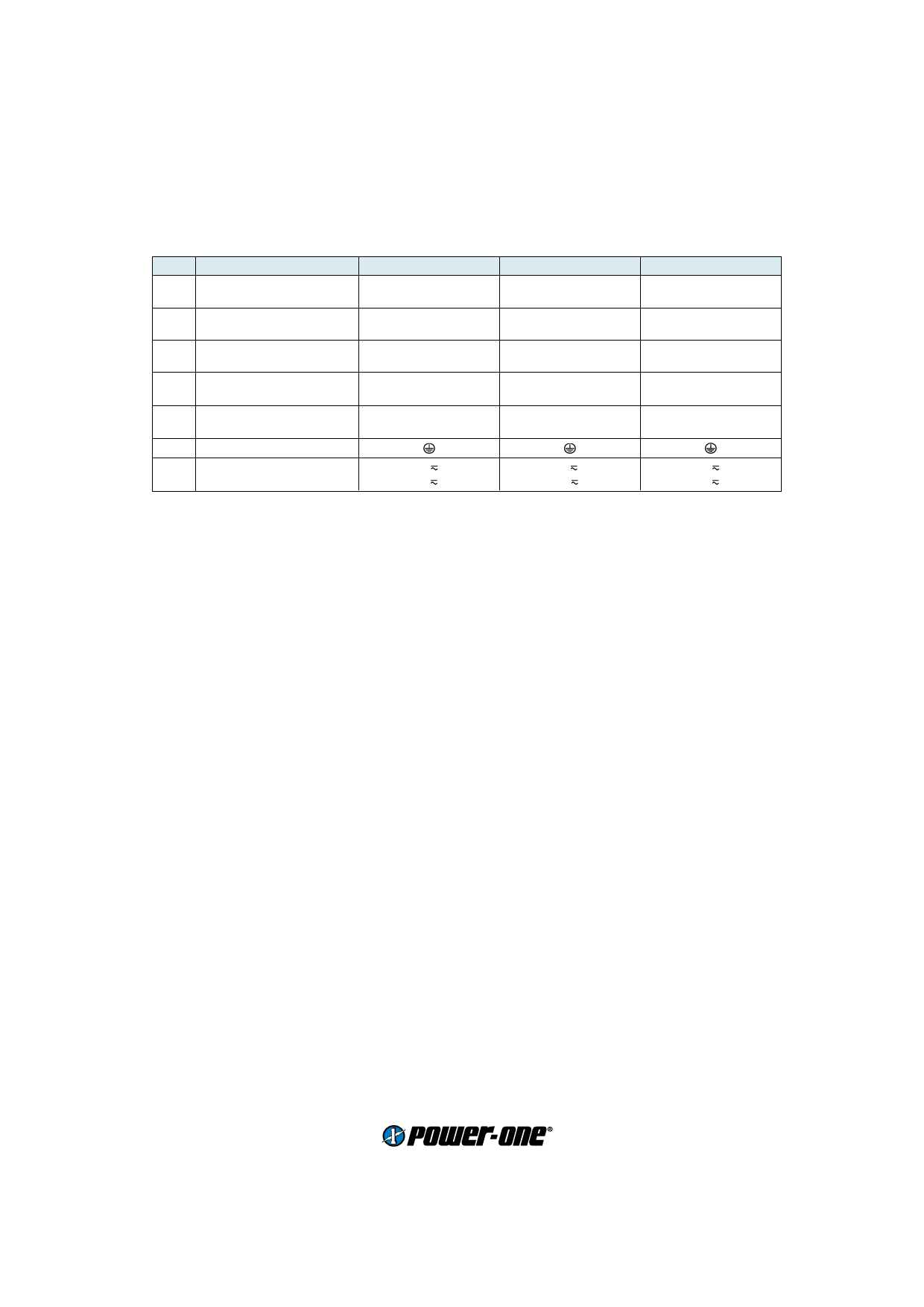
Pin allocation
Pin Electrical Determination
2 Inhibit control input
5 Safe Data or ACFAIL
8 Output voltage (positive)
11 Output voltage (negative)
14 Control input +
17 Control input –
14 Output voltage (positive)
17 Output voltage (negative)
20 Output voltage (positive)
23 Output voltage (negative)
26 Protective earth
29 AC input voltage
32 AC input voltage
LH1000
i
D or V
Vo1+
Vo1–
R
G
Vo1+
Vo1–
N
P
LH2000
i
D or V
Vo2+
Vo2–
Vo1+
Vo1–
N
P
LH3000
i
D or V
Vo3+
Vo3–
Vo2+
Vo2–
Vo1+
Vo1–
N
P
Accessories
Front panels 19" (Schroff/Intermas)
Mating H11 connectors with screw, solder, fast-on or press-fit terminals
Connector retention facilities and code key system for connector coding
Flexible PCB for connecting the converter via an H11 connector, if mounted on a PCB
Chassis or wall mounting plates for frontal access
Universal mounting brackets for chassis or DIN-rail mounting
www.power-one.com
Edition 4/04.2001
2/12.2000
4
Share Link: 