LC201V02 Просмотр технического описания (PDF) - Philips Electronics
Номер в каталоге
Компоненты Описание
производитель
LC201V02 Datasheet PDF : 26 Pages
| |||
Product Specification
LC201V02
Liquid Crystal Display
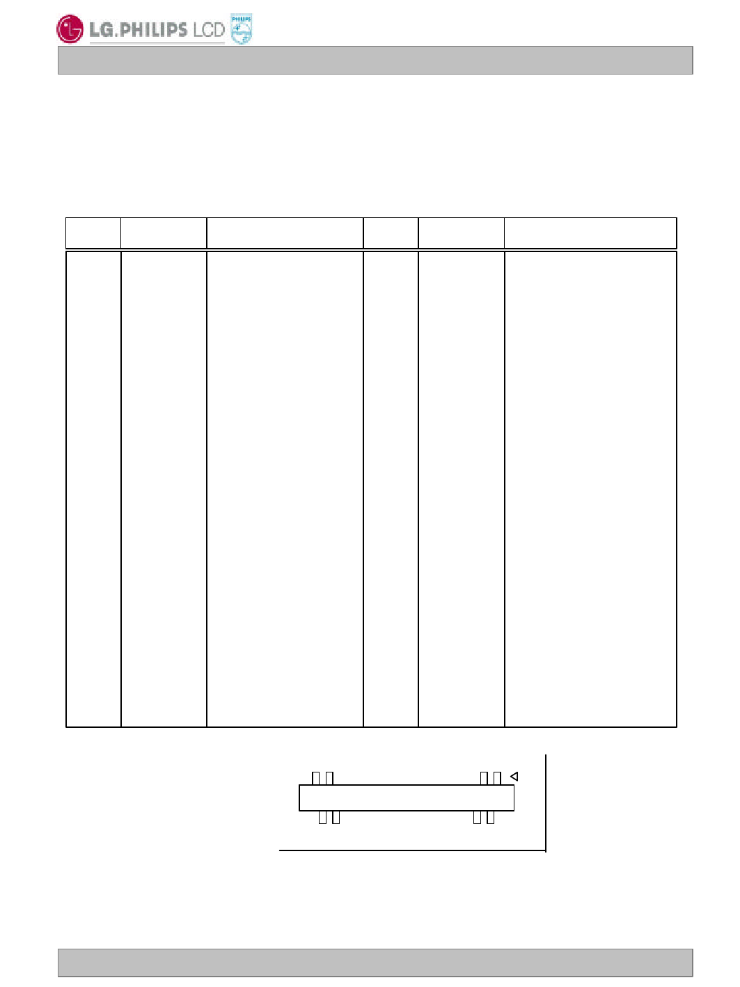
3-2. Interface Connections
- LCD Connector(CN1):DF9B-41P-1V (Manufactured by Hirose) or Equivalent
- Mating Connector : DF9B-41S-1V (Manufactured by Hirose) or Equivalent
Table 3. MODULE CONNECTOR(CN1) PIN CONFIGURATION
Pin No Symbol
Description
1 RBF
2 DCLK
3 GND
4 Hsync
5 Vsync
6 GND
7 R0
8 R1
9 R2
10 R3
11 R4
12 GND
13 R5
14 R6
15 R7
16 G0
17 GND
18 G1
19 G2
20 G3
NC 1)
Dot Clock
System Ground 2)
Horizontal Sync
Vertical Sync
Red Data(LSB)
System Ground
Red Data(MSB)
Green Data(LSB)
System Ground
Pin No Symbol
Description
21 G4
22 GND
23 G5
24 G6
25 G7
26 B0
27 GND
28 B1
29 B2
30 B3
31 B4
32 GND
33 B5
34 B6
35 B7
36 GND
37 DE
38 GND
39 VLCD
40 VLCD
41 VLCD
System Ground
Green Data(MSB)
Blue Data(LSB)
System Ground
System Ground
Blue Data(MSB)
System Ground
Data Enable
System Ground
Power input(+12.0V)
Power input(+12.0V)
Power input(+12.0V)
41
1
Rear view of LCM
40
2
Note: 1. NC: No Connection.
2. All GND(ground) pins should be connected together and to Vss which should also be connected to
the LCD’s metal frame.
3. All VLCD (power input) pins should be connected together.
Ver. 0.1
Jan. 17, 2003
9 / 26
Share Link: 