LB11820 Просмотр технического описания (PDF) - SANYO -> Panasonic
Номер в каталоге
Компоненты Описание
производитель
LB11820 Datasheet PDF : 17 Pages
| |||
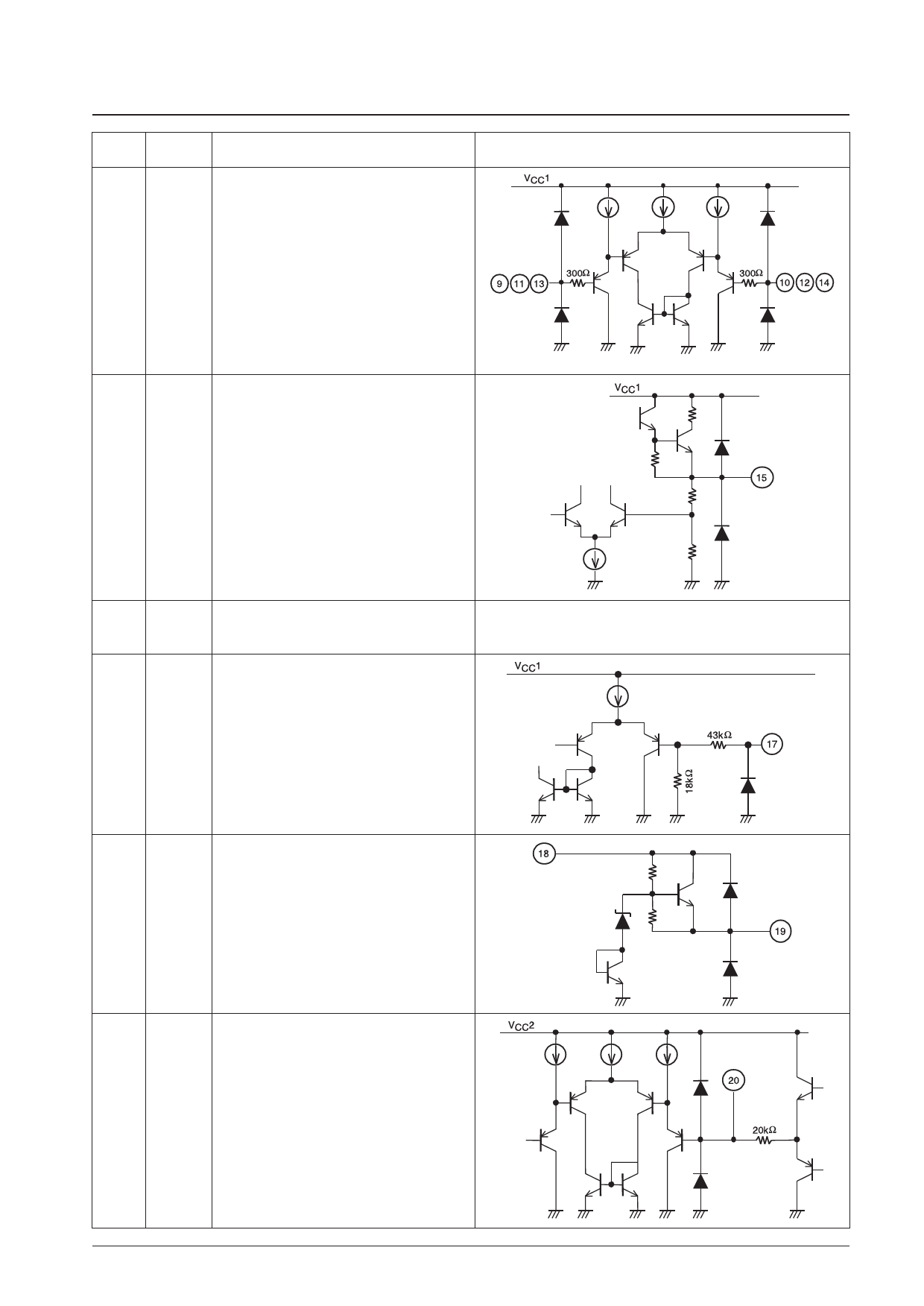
Continued from preceding page.
Pin No.
Pin
Function
LB11820M
9
IN1+ Hall amplifier input.
10
IN1– IN+ > IN– is the input high state, and the reverse is
11
IN2+ the input low state.
12
IN2– Connect a capacitor between the sIN+ and IN–
13
IN3+
inputs if there is noise in the Hall sensor signals.
14
IN3–
15
VREG Regulated-voltage output pin (5V output)
Connect a capacitor (about 0.1 µF) between this pin
and ground for stabilization.
Equivalent circuit
16
VCC2 Power pin (PWM oscillation, PWM comparator,
VCTL amp). Normally connect to VREG.
17
LVS Voltage detection pin for low-voltage protection.
To detect the supply voltage of 5 V or more, connect
the zenor diode in series to set the detection voltage.
18
VCC3 Power pin (VCC3) for use during application with the
19
12REG supply voltage of 12 V or more. 12 V is generated at
the 12 REG pin. To use the 12REG pin, connect this
pin to VCC1.
When not used, keep both VCC3 and 12 REG open
or connect them to GND.
20
TOC PWM waveform comparator pin.
Normally used in the open condition.
By inputting the voltage directly into this pin, the
output duty can be controlled without using the
VCTL amp.
Continued on next page.
No. 7104-7/17
Share Link: 