LA75521VA Просмотр технического описания (PDF) - SANYO -> Panasonic
Номер в каталоге
Компоненты Описание
производитель
LA75521VA
SANYO -> Panasonic

LA75521VA Datasheet PDF : 13 Pages
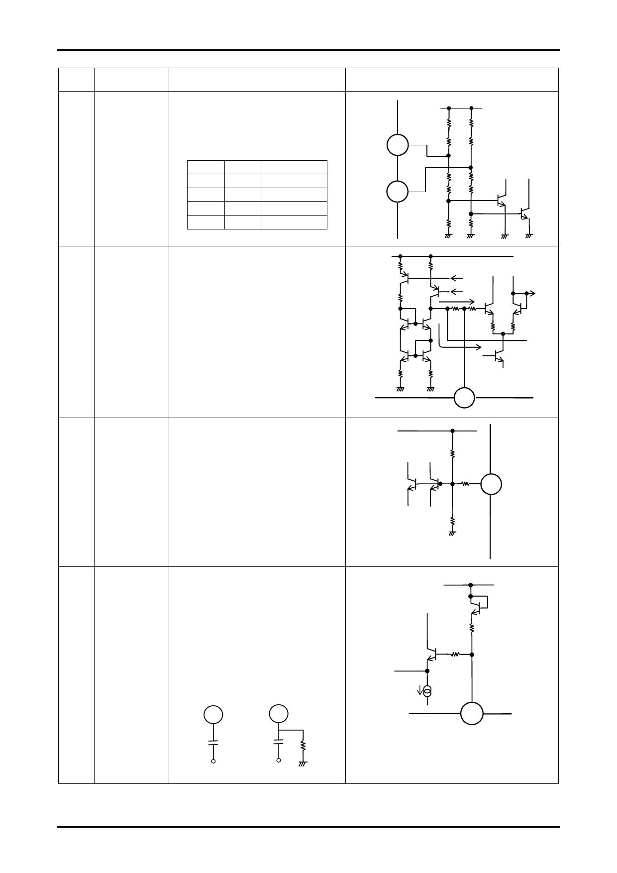
| |||
LA75521VA
Continued from preceding page.
Pin
Pin name
No.
Function
7
SIF SYSTEM SW A SIF system selection switch pins. Combining the
9
SIF SYSTEM SW B settings of these two pins supports four systems.
In M/N mode, the audio output level is increased
by 6dB.
The internal trap is also linked to these switches.
The truth-values are as follows.
Pin 7
Pin 9
MODE
H
H
M
H
L
I
L
H
B/G
L
L
D/K
8
APC FILTER
PLL APC filter connection pin. The APC count is
switched internally in the IC.
The VCO is normally controlled by route A.
When unlocked and during weak field reception,
the VCO is controlled by route B and the loop gain
is increased.
For this APC filter we recommend a resistor of 51Ω
and capacitor of 0.47μF.
The buzz characteristics can be improved by
connecting a capacitor of 100pF or so between
pins 5 and 8.
10
VIF FREQUENCY SW Switch pin for selecting the IF frequency
When this pin is open, 1/2VCC exists.
VCC: 39.5MHz
Open: 38.9MHz
GND: 38.0MHz
Equivalent Circuit
A7
50kΩ
1kΩ
B9
1kΩ
80kΩ
30kΩ
50kΩ
1kΩ
1kΩ
80kΩ
30kΩ
FROM
APC
A DET
1kΩ 1kΩ
B
8
50kΩ
10
11kΩ
50kΩ
11
REFERENCE CP Reference signal input pin necessary for adjusting
INPUT
the internal sound carrier trap, AFT, etc.
Either 4.0 or 4.43MHz can be selected. Use the
configuration shown in example 1 when using
4.43MHz and configuration shown in example 2
when using 4.0MHz.
Since no oscillator can be configured simply by
connecting the X’tal resonator to pin 11, input the
reference signal from an external source without
fail.
Example 1
11
Example 2
11
1000pF
4.43M
1000pF
4.0MHz
270kΩ
200kΩ
11
Continued on next page.
No.A1004-9/13
Share Link: