HT813D0 Просмотр технического описания (PDF) - Holtek Semiconductor
Номер в каталоге
Компоненты Описание
производитель
HT813D0 Datasheet PDF : 12 Pages
| |||
HT813D0
• Busy output
When a voice group is playing, the outputs of
both FLAG1 and FLAG2 are turned low, indi-
cating that the chip is busy.
In addition to the above-stated output signals,
FLAG1 can also generate one of the following
signals by code option:
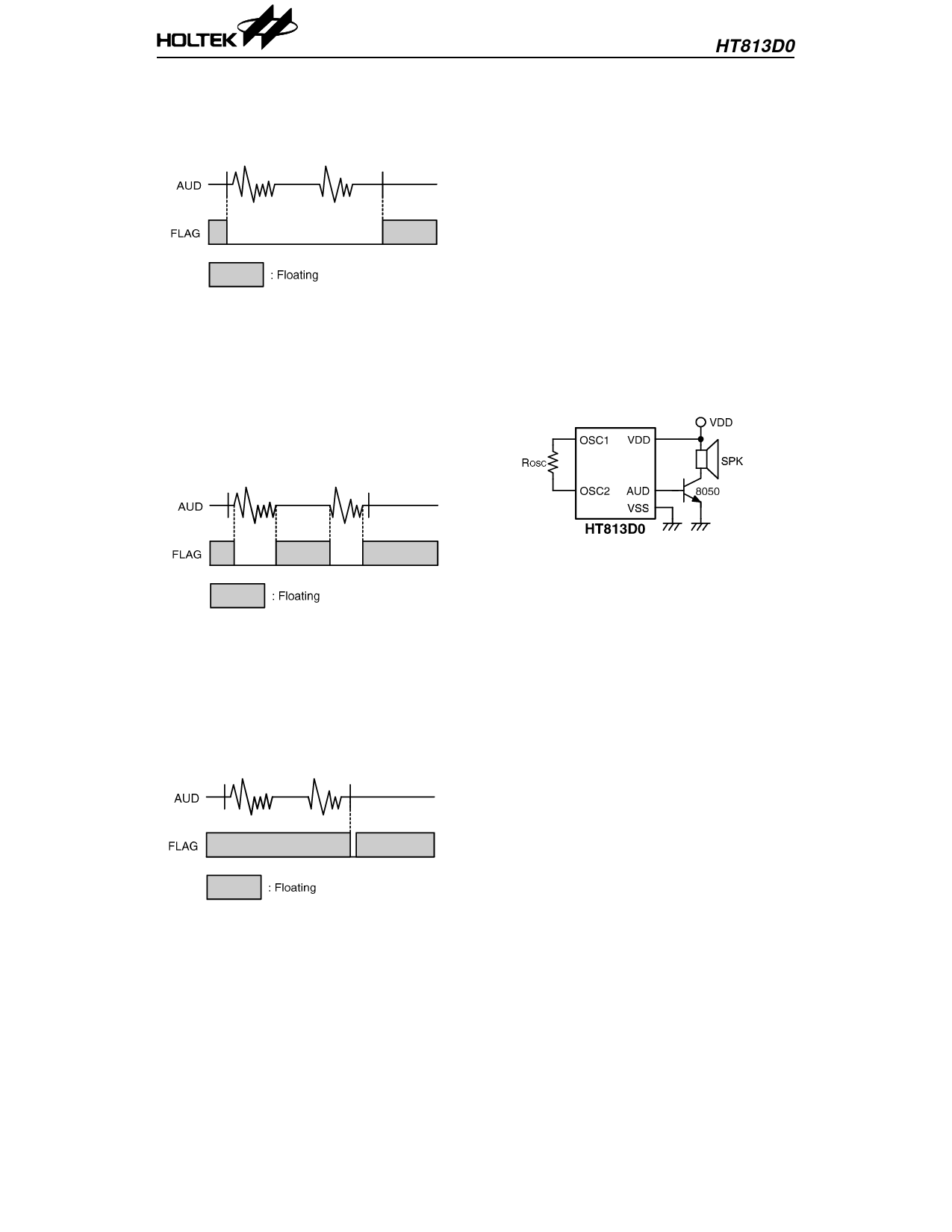
• Voice indicator output
FLAG1 is active low when voices are playing.
FLAG1 is also turned low when a voice section
is output. The brightness of FLAG1 varies
with the volume. FLAG1 becomes floating af-
ter the silence section is output or the voice
output is terminated.
Volume control
The function of the volume control can be set by
mask option. A code is written in the function
table for the purpose of controlling the volume
of each section output after the volume control
function is chosen. There are two volume op-
tions, namely, full range and half range.
AUD
The AUD pin is a PMOS open drain structure.
It outputs voice signals to drive a speaker
through an external NPN transistor when the
chip is active. However, the AUD pin becomes a
floating output when the chip is in the standby
state.
The 8050 type transistor with hFE≅150 is rec-
ommended for an output driver.
• End-pulse output
When the voice output is completed, the
FLAG1 pin outputs an active low pulse. The
pulse width can be programmed depending on
the customer’s requirements.
The FLAG1 as well as FLAG2 pins are both
floating outputs when the chip is in the
standby state.
8
5th May ’98
Share Link: 