L5994 Просмотр технического описания (PDF) - STMicroelectronics
Номер в каталоге
Компоненты Описание
производитель
L5994 Datasheet PDF : 26 Pages
| |||
L5994 - L5994A
the oscillator. That turns off the low-side MOSFET (synchronous rectifier) and, when the low-side gate voltage
falls below 0.3V to prevent cross-conduction, turns on the high-side one, thus allowing energy to be drawn from
the input source and stored in the inductor.
The error summing, by comparing the above mentioned signals, determines the moment in which the output
latch is to be reset. The high-side MOSFET is then turned off and the synchronous rectifier is turned on when
the voltage on the high-side MOSFET source falls below 2V to prevent cross-conduction, thus making the in-
ductor current recirculate. The high side mosfet is in any case turned off on the clock signal falling edge: this is
the reason why the duty cicle is limited in its maximum value.
The reached state is maintained until the next oscillator pulse.
The open-loop transfer function of such a kind of control system, under the assumption of an ideal slope com-
pensation, is:
F(s) = A ⋅ 2-----⋅---R--R---s--o-e---n---s---e- ⋅ -(--1-----+-----s----⋅---R--1---o--+--⋅---Cs----o-⋅---E)---⋅-S--(---R1----+-⋅---C-s----O-⋅---R----F-----⋅---C----F----)
where A is the gain of the error summing comparator, which is 2 by design.
The system is inherently very fast since it tends to correct output voltage deviations nearly on a cycle-by-cycle
basis. Actually, in case of line or load changes, few switching cycles can be sufficient for the transient to expire.
The operation above illustrated is modified during particular or anomalous conditions. Leaving out other circum-
stances (described in "Protections" section) for the moment, consider when the load current is low enough or
during the first switching cycles at start-up: the inductor current may become discontinuous, so it is zero during
the last part of each cycle. In such a case, a "zero current comparator" detects the event and turns off the syn-
chronous rectifier, avoiding inductor current reversal and reproducing the natural turn-off of a diode when re-
verse biased. This allows to increase the efficiency in ligth load. Both MOSFET's stay in off state until the next
oscillator pulse.
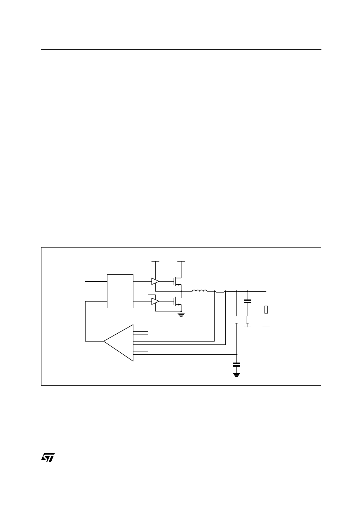
Figure 3. Control loop.
HSTRAP
Vin
`CLOCK
S
Q
REG5
R
NQ
+
-
ERROR
SUMMING
+
-
+
-
SLOPE
COMPENSATION
VREF
L
Rsense
Co
Ro
Rf ESR
Cf
Synchronous Rectification
Very high efficiency is achieved at high load current with the synchronous rectification technique, which is par-
ticularly advantageous because of the low output voltage. The low-side MOSFET, that is the synchronous rec-
tifier, is selected with a very low on-resistance, so that the paralleled Schottky diode is not turned on, except for
the small time in which neither MOSFET is conducting. The effect is a considerable reduction of power loss dur-
ing the recirculation period.
9/26
Share Link: 